High Speed Milling Parameters
Common Parameters for High Speed Rough, Rest Rough, Finish, and Rest Finish Sequences
• AXIS_SHIFT — Specify the axis shift of the tool along the work piece. Allows you to shift the CL data along the tool axis. If set to a positive value, all CL data shifts down along the tool axis; a negative value shifts the CL data up.
Default: 0
• BOTTOM_STOCK_ALLOW — Specify the amount of stock to be left after a sequence on planar surfaces parallel to the retract plane.
Default: -
• CLEAR_DIST— Specify the clearance distance above the surface to be milled at which the rapid motion ends and the appropriate feed begins.
Default: Based on internal relation after defining tool.
• CUT_ANGLE — Specify the angle between the cut direction and the X-axis of the NC Sequence coordinate system. The parameter is not available for 3+2 axis machining type.
Default: 0
Only TYPE_1 value is applicable for SCAN_TYPE parameter in HSM Rough and HSM Rest Rough. Similarly, the PARALLEL_CUTS value is applicable for HSM Finish and HSM Rest Finish sequences.
• CUT_TYPE — Specify the cut type. Combined with SPINDLE_SENSE, this parameter controls where the material is relative to the tool when the tool removes material.
Default: Climb
The following options are available—
◦ Upcut
◦ Zig-Zag
◦ Spiral — Available in HSM Finish, HSM Rest Finish, and 5 axis roughing sequences. It is not supported for PARALLEL_CUTS and FLAT_LANDS options.
• END_HEIGHT — Specify the end height for slices. The parameter is not available for 3+2 axis machining type.
Default: -
• HOLDER_CLEARANCE — Specify the minimum allowable distance between the tool holder and the machined surface. The parameter works in combination with any stock clearance defined.
Default: 0.2 mm. For 3+2 axis roughing and rest roughing, converted 5 axis finishing and rest finishing, auto deburring, and 5 axis roughing and rest roughing steps, the default value of this parameter is 2 mm.
• PULLOUT_DIST — Specify the height above the level of the cut, for example, the slice just milled, up to which the tip of the tool retracts at PULLOUT_FEED and then changes to FREE_FEED. If PULLOUT_FEED is not defined, the tool retracts at CUT_FEED and then changes to FREE_FEED. If FREE_FEED is not defined, the tool retracts at Rapid.
Default: -
• SCALLOP_HGT — Specify the maximum allowable scallop height to control the tool step over. This parameter is applicable for horizontal step over passes and all scan types except CONSTANT_LOAD.
Default: -
• SLICE_PATH_SCAN — Specify the order of machining multiple passes within multiple step depths or slices.
Default: PASS_BY_PASS
The following options are available—
◦ PASS_BY_PASS — Activates region-wise machining. The tool completes all slices in one region and then moves to machine the next region.
◦ SLICE_BY_SLICE — Activates slice-wise machining. All the first slices of the regions are one-by-one machined leading on to the second slices.
• START_HEIGHT — Specify the start height for slices. The parameter is not available for 3+2 axis machining type.
Default: -
• STEP_OVER — Specify the parameter to control the lateral depth of cut.
Default: Based on the internal relation after defining tool.
For CONSTANT_LOAD scan type, the step over becomes the maximum step over. Depending on the tool load, the step over value might be decreased. For CONSTANT_LOAD scan type, it is recommended that the STEP_OVER value must be less than or equal to 50 percent of cutter diameter.
The STEP_OVER must be a positive value less than or equal to the cutter diameter.
• TOLERANCE — Machine tools move in small straight line increments to approximate curved geometry. Specify the maximum distance that the straight line path deviates from the curved geometry.
Default: 0.06 mm in HSM Rough and HSM Rest Rough.
Default: 0.025 mm in HSM Finish and HSM Rest Finish.
• TRIM_TOOLPATH_ON_HOLDER — Divide the tool path into colliding and non-colliding zones provided that the HOLDER_DIAMETER and HOLDER_LENGTH parameters are set. In the colliding zone, the tool holder collides with the reference part and the toolpath gets trimmed, whereas there is no collision in the non-colliding zone. The resultant tool path is the combination of all non-colliding zones.
Default: Yes
In HSM Rough and HSM Rest Rough sequences, this parameter is not supported if the SCAN_TYPE is set to TYPE_1 and the ROUGH_OPTION is set to ROUGH_ONLY.
HSM Rough and HSM Rest Rough Parameters for Cutting Motions
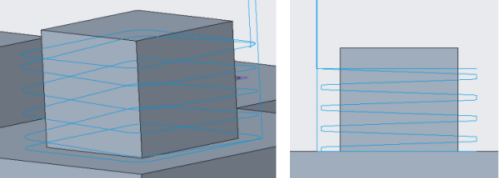
• SCAN_TYPE — Specify the way a milling tool scans the horizontal cross-section of a milling volume and avoids islands.
Default: CONSTANT_LOAD
The following options are available—
◦ TYPE_1 — Creates parallel cuts on multiple depths. This option is not available for 3+2 axis machining type.
The SCAN_TYPE changes to CONSTANT_LOAD from TYPE_1 when you select 3+2 axis machining. If you switch back to 3 axis machining from 3+2 axis machining, CONSTANT_LOAD scan type remains effective. |
◦ TYPE_SPIRAL — Generates a spiral cutter path.
◦ CONSTANT_LOAD — Ensures that the cutting conditions remain almost constant. This offers improvements over conventional constant offset roughing strategies. The strategy avoids full-width cuts by constantly measuring the engagement volume of the tool with material, and gradually removing material from the remaining stock. The stable load on the tool allows an increased material removal rate at higher feed rates and reduces the overall machining time.
• ROUGH_OPTION — Specify whether a profiling pass must occur during roughing or rest roughing. The parameter is not available for 3+2 axis roughing sequences and by default it creates sequences with no profiling pass.
Default: ROUGH_ONLY
◦ ROUGH_ONLY — Create an NC sequence with no profiling.
◦ ROUGH_&_PROF — Create an NC sequence that rough cuts and profiles the stock in Mill window. It applies to TYPE_1 scan type.
• INTERMEDIATE_SLICE_ADJUST — Define when the intermediate slices must be created. Use this option in combination with the NUMBER_INTERMEDIATE_SLICES parameter.
Default: DURING
◦ DURING — Create intermediate slices during machining passes.
◦ AFTER — Create intermediate slices after the last slice is machined.
• TRIM_TO_WORKPIECE — Click YES to confine the toolpath to workpiece boundaries to avoid air machining.
Default: NO
HSM Rough and HSM Rest Rough Parameters for Cut Depth and Allowances
• ROUGH_STOCK_ALLOW — Define the amount of stock to be left in the radial direction after the rough cut.
Default: 0
• MAX_STEP_DEPTH — Specify the maximum allowed step depth. After finding the positions of the highest and lowest slices, the actual step depth is calculated, which is less than or equal to the specified MAX_STEP_DEPTH.
Default: Based on internal relation after defining tool
You can change the relation from the Relations dialog box or specify the value.
• MACHINE_FLATLANDS — Select to machine true flat surfaces of the mold parts. This option helps you to machine flat surfaces on Z axis such as parting surfaces.
Default: YES
If set to NO, it creates constant Z slices without adjusting the step depth. In such a case, stock may remain on the flat surfaces, which can be more or less of defined allowed bottom stock.
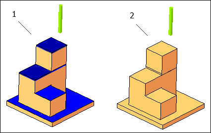
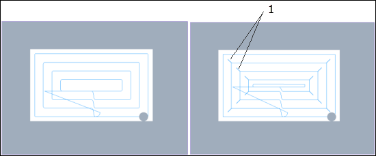
1. The option set to NO. The blue surfaces in the image indicate the material left after machining.
2. The option set to YES. All flat surfaces are machined without leaving any material.
• MINIMUM_WIDTH — Specify the minimum width. Areas that have a width smaller than the specified width are not machined. Applicable when MACHINE_FLATLANDS is activated.
Default: 1 mm
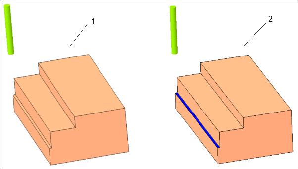
1. Minimum width is set to 0. All flat surfaces are machined without leaving any material.
2. Flat areas that have less than the specified width are not machined. The width of blue surface is less than the specified width.
• FILTER_TYPE — Select the type of region to be filtered out while machining. It is specified in relation with the threshold percentage of the tool diameter. It is used to avoid machining of unnecessary regions.
Default: INSCRIBED_CIRCLE
The following options are available—
◦ INSCRIBED_CIRCLE — Indicates that the maximum region width filtered is a circle diameter, which is inscribed into toolpath within such a region.
◦ DIAGONAL_LENGTH — Indicates that the maximum region width is a diagonal of axis-aligned bounding box built around the toolpath within this region.
• THRESHOLD_VALUE_PERCENT — Specify the threshold value in percent of the tool diameter. This value determines the width of a region to be filtered out while machining.
Default: 0 percent
This works in combination with the FILTER_TYPE parameter.
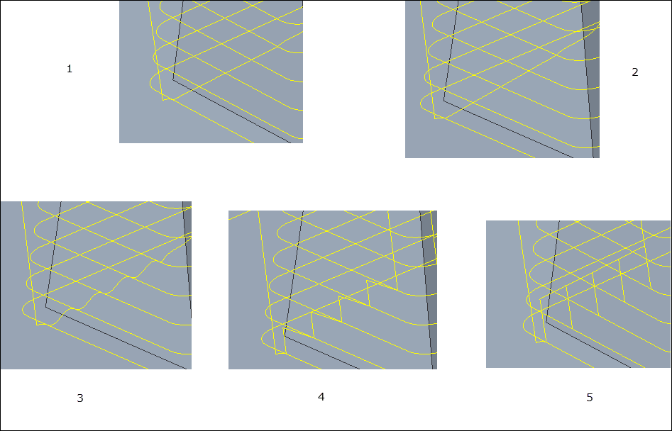
• REMOVE_CORNER_PEGS — Select to add extra toolpath around the corners that removes small pegs of material in the corners. These pegs are observed when the step over is large enough to leave the material between passes.
Default: NO
It applies to TYPE_SPIRAL scan type.
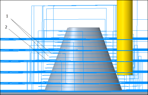
1. Extra toolpath that removes corner pegs
• NUMBER_INTERMEDIATE_SLICES — Specify the number of slices to be created. The intermediate slice is a Profile slice between the rough slices. The INTERMEDIATE_SLICE_ADJUST parameter dictates when the slices are created.
Default: 0
It does not apply to vertical geometry.
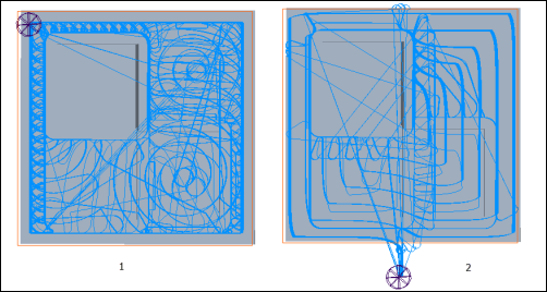
1. The parameter value 2 results into creation of two intermediate slices
2. Main rough cut
• DETECT_THICKER_THAN — Specify the thickness. It allows to avoid machining of the areas where amount of stock material is less then specified thickness threshold value.
Applicable only for Rest Rough sequences.
Default: 0.1 mm
• PREVIOUS_ROUGH_STOCK_ALLOW — Specify the amount of stock left by the previous roughing portion of the toolpath.
Applicable only when Reference Cutting Tool is selected as a reference on the References tab. The parameter is not available for 3+2 axis machining type.
Default: 0
• PREVIOUS_BOTTOM_STOCK_ALLOW — Specify the amount of stock left by the previous roughing portion of the toolpath on the surface parallel to the retract plane.
Applicable only when Reference Cutting Tool is selected as a reference on the References tab. The parameter is not available for 3+2 axis machining type.
Default: 0
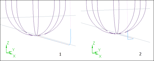
• ALLOW_ENTRY_OUTSIDE — Select YES to allow the tool to enter from outside the stock or mill window. The parameter is not available for 3+2 axis machining type.
Default: YES
If set to NO, the tool does not enter from outside the stock or Mill window even when it is possible. Mill Window options—Inside window contour, On window contour, and Outside window contour are available when this parameter is set to NO.
1. Tool engages on the material when the option is set to NO.
2. Tool approaches from outside when the option is set to YES.
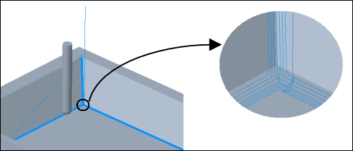
• LIFT_TOOL_CLEARANCE — The tool lifts to clear above the machining surface to make the next connection. The connection moves are in RAPID feed or FREE feed. This works together with MIN_RETRACT_DISTANCE.
Default: -. It is interpreted as 0.5 mm or 0.02 in inches.
When value is set to 0, the tool does not lift above the machining surface to make the next connection. The connection moves are in CUT feed. |
• MIN_RETRACT_DISTANCE — When moving between the end of one pass and the beginning of another, the cutter is either on the surface or it is in retraction, depending on the distance it has to travel. The parameter here controls the point where the decision between the two states is made. If the distance between the end point of one pass and the start point of another is less than this value, the cutter does not retract. If the distance is greater, the cutter clears to the retract plane.
This parameter works for CONSTANT_LOAD scan type.
Default: -. It is interpreted as (5 * tool diameter)
HSM Rough and HSM Rest Rough Parameters for Entry/Exit Motions
• CLOSED_AREA_ENTRY — Specify the entry method for closed areas.
Default: Automatic
The following options are available—
◦ Automatic — Tool takes the best suited entry for closed area.
◦ Helical — Tool enters a closed area by following a helical trajectory. The diameter of the helix is specified by the HELICAL_DIAMETER_PERC parameter.
◦ Radial — Tool radially engages with the stock in a closed area. This option does not work with CONSTANT_LOAD.
When all the types of entry to close area fail, it automatically takes the Zig-Zag ramping. |
• RAMP_ANGLE — Specify the angle with which the tool enters the next slice or pass.
Default: 5
• HELICAL_DIAMETER_PERC — Specify the maximum allowed helix diameter in percent of the tool diameter. This applies for helical entry of the tool.
Default: 80 percent
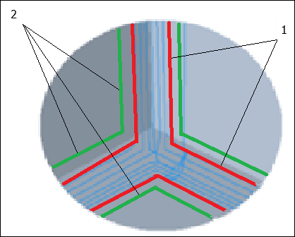
• ALLOW_TOOL_OUTSIDE_WORKPIECE — Specify whether the tool can go past the workpiece boundary when the mill window is greater than the workpiece. When set to NO, the tool enters from outside of the workpiece but exits on the workpiece. The toolpath around the workpiece is generated only when the unmachined stock is greater than the sum of tolerance, stock allowance, and tool radius.
As shown in the next image, when the parameter is set to YES, the toolpath goes past the workpiece.
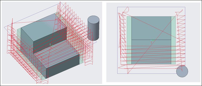
As shown in the next image, when the parameter is set to NO, the toolpath starts from outside the workpiece but ends on the workpiece.
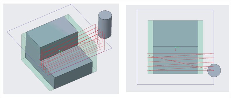
Default : YES
This parameter works for TYPE_1 scan type.
HSM Rough and HSM Rest Rough Parameters for Machine Settings
• SMOOTH_RADIUS — Specify the radius for filleting or smooth corner machining. This parameter is applicable when SCAN_TYPE parameter is set to CONSTANT_LOAD.
Default: -. The default value - is interpreted as 1.
The value must be greater than 0.
• CIRC_INTERPOLATION — Specify the CL data format for circular edges. The parameter is not available for 3+2 axis machining type.
Default: ARC_ONLY.
HSM Finish and HSM Rest Finish Parameters for Entry/Exit Motions
• LEAD_RADIUS — Specify the radius of the tangential circular movement of the tool when leading in or out.
Default: 0
• CUT_ENTRY_EXIT_EXT — Select the approach direction of the tool.
Default: TANGENTIAL_ARC
The following options are available—
◦ NONE — Tool enters or exits without any lead in and out motion.
◦ TANGENTIAL_ARC — Tool takes horizontal arc for steep areas and vertical arc for shallow areas while leading in and out.
◦ VERTICAL_TANG_ARC — Tool takes vertical arc for all areas while leading in and out.
◦ HORIZONTAL_TANG_ARC — Tool takes horizontal arc for all areas while leading in and out
◦ AUTOMATIC_ARC— Tool automatically tilts in an arc to avoid collisions in lead-in and lead-out moves. This option is available only for converted 5 axis sequences.
1. VERTICAL_TANG_ARC
2. HORIZONTAL_TANG_ARC
• SMALL_LINKS — Specify the connection type between adjacent cuts or cutting layers.
Default: BLEND_SPLINE
The following options are available—
◦ DIRECT — Creates the shortest connection in a straight line between the gap edges, without any retracting movements.
◦ FOLLOW_SURFACE — Creates a connection that follows the existing geometry on the gap edges, without any retracting movements.
◦ BLEND_SPLINE — Creates a connection in tangential arcs between the gap edges.
◦ STEP — The option involves retraction, connection, and vertical approach segments. Creates a connection in the tool plane between the gap edges.
◦ RETRACT_TO_CLEAR_DIST — Creates a connection in straight line between the gap edges. The tool retracts to the specified clear distance.
◦ RETRACT_TO_RETRACT_PLANE — Creates a connection in straight line between the gap edges. The tool retracts to the retract plane. The option involves segments such as retracting of a tool along the tool axis to retract plane, connection, and approach along the tool axis.
If the selected link type does not satisfy the safety conditions, next safe link type is used. |
1. DIRECT
2. FOLLOW_SURFACE
3. BLEND_SPLINE
4. STEP
5. RETRACT_TO_CLEAR_DIST
HSM Finish and HSM Rest Finish Parameters for Cutting Motions
• FINISH_OPTION — Specify the machining method to create an optimized tool path.
Default: SMART_CUTS
The following options are available—
◦ CONSTANT_Z — Finishes vertical surfaces or steep areas.
◦ CONSTNAT_CUSP — Creates equidistant cusps in steep as well as shallow areas. The aim is to have a constant distance between each contour so that the cusps are created with the equal height.
◦ SMART_CUTS — Creates combined toolpath which consists of Constant Z slices for steep areas and Constant cusp cuts for shallow areas of a part.
◦ PARALLEL_CUTS — Creates parallel cuts on X-Y plane. Use it for shallow areas.
◦ FLAT_LANDS — Creates toolpath to machine true flat regions of stock. Applicable only for Finish Sequences.
◦ PENCIL_CUT — Creates single toolpath for the inlaying edges. Application only for Rest Finish sequences.
1. CONSTNAT_CUSP
2. CONSTANT_Z
3. FLAT_LANDS
4. PARALLEL_CUTS
• SPIRAL_SCAN_DIRECTION — Specify the direction of the toolpath for spiral scan.
Default: OUTSIDE_IN
The following options are available—
◦ OUTSIDE_IN — From border to the center
◦ INSIDE_OUT — From center to the border
HSM Finish and HSM Rest Finish Parameters for Cut Depth and Allowances
• STEEP_STEP_OVER — Specify the value of step over when machining a steep area. If a value is not specified for STEEP_STEP_OVER, then the STEP_OVER value is used as the STEEP_STEP_OVER value.
Default: -
• FINISH_STOCK_ALLOW — Specify the amount of stock to be left after machining.
Default: -
• REST_AREA_OFFSET — Specify the offset value to be applied to the computed rest area. The rest material area is calculated based on the previous tool used.
Applicable only for Rest Finish sequences.
Default: 0
1. The actual machining area calculated based on previous tool.
2. Possible machinable area after setting the Rest Area Offset.
• SLOPE_ANGLE_START — Specify the start angle. The SLOPE_ANGLE_START and SLOPE_ANGLE_END form an interval. You can machine surfaces that fall in or out of this interval. The steep areas and shallow areas are detected automatically. The view direction and the angles that form the interval define these areas.
Default: -
◦ Start angle must be smaller than the end angle.
◦ If the step over value is greater than the area you defined by the start and end angles, toolpath is not generated.
• SLOPE_ANGLE_END — Refer to SLOPE_ANGLE_START described previously.
Default: -
• OPTIMAL_ANGLE — Select YES to automatically determine the direction where the number of cuts will be minimal.
Default: NO
This parameter applies only to PARALLEL_CUTS parameter in Finish and Rest Finish sequences.
• MULTI_PENCIL_PASSES — Specify the number of passes on each side of the pencil cuts.
Applicable only for Rest Finish sequences.
Default: 0
• DETECT_THICKER_THAN —Specify the thickness. It allows you to avoid machining of the areas where amount of stock material is less than the specified thickness threshold value.
Default: 0.1 mm
Auto Deburring Parameters for Cutting Motions
• EDGE_THICKNESS — Specify the thickness of the chamfer on the machined edges.
Default: 0.5 mm
• EDGE_EXTENSION — Specify the extension length for the edge that you are machining. The extension is added at both ends of the edge. The tool traverses till the extended edge while machining.
Default: 0
• RELIEF_CORNER — Select a method to machine inner edges of the reference part.
Default: NONE
The following options are available:
◦ NONE — By default no loop or arc is added when the tool traverses through inner edges.
◦ ADD_LOOP — Loops are added to the toolpath for the tool to smoothly traverse through the inner edges.
◦ NO_LOOP — Arcs are added to the toolpath for the tool to smoothly traverse through the inner edges.
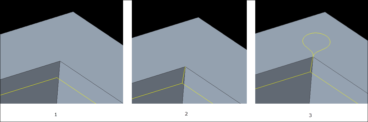
1. NONE
2. NO_LOOP
3. ADD_LOOP
• INNER_LOOP_RADIUS — Specify the loop radius if you have selected ADD_LOOP to add loops to the toolpath.
Default: 2 mm
• MIN_DETECT_EDGE_LENGTH — Specify the minimum length of an edge required for the tool to detect the edge for machining. Edges shorter than the specified length are not machined.
Default: -
• MIN_EDGE_ANGLE — Specify the minimum edge angle to detect the sharp edges to be machined on the part. Edges with angle greater than the specified angle are classified as sharp edges.
• NUMBER_CUTS — Specify the number of cuts along a sharp edge to approximate the flat shape or chamfer on the edge. Number of slices are calculated as EDGE_THICKNESS/NUMBER_CUTS. For example, if the EDGE_THICKNESS is 2.0 mm and NUMBER_CUTS is 4, the edge will be machined in four equal slices of value 0.5 mm to achieve the edge thickness.
Auto Deburring Parameters for Entry/Exit Motions
• RAPID_DISTANCE — Specify the distance from which the tool retracts or approaches at a rapid or free feed along the axis. This parameter is available in both 3 axis and 5 axis Deburring sequences, however applicable only for 5 axis Deburring sequences. Rapid distance includes the clear distance.
Default: 20 mm
• LINK_TYPE — Select one of the following two retract strategies between toolpath segments.
◦ RETRACT_BLEND_SPLINE — Tool retracts along the blend spline to create smooth transitions.
◦ RETRACT_TO_CLEARANCE — Tool retracts to the automatically defined retract area for the AUTOMATIC retract type or the tool retracts with specified retract strategy.
HSM 5 Axis Rough and Rest Rough Parameters
• RAPID_DISTANCE — Specify the distance from which the tool retracts or approaches at a rapid feed along the axis. Rapid distance includes the clear distance and pullout distance.
Default: 20 mm
• MAX_STEP_OVER — Specify the maximum step over of the tool. Maximum step over is calculated by default as you select a tool.
• FIRST_STEP_DEPTH — Specify how deep you want the first cut. After the first cut, the tool uses STEP_DEPTH value to make successive cuts.
Default: 0. Not applicable for Morph slice generation strategy.
• LAST_STEP_DEPTH — Specify how deep you want the last cut. You can cut up to a certain distance from the floor surface.
Default: 0. Not applicable for Morph slice generation strategy.
• MACHINE_BY — Select one of the following machining options:
◦ REGIONS —Every region is separately machined.
◦ LEVELS —All regions are simultaneously machined in successive levels.
• ROUGH_STOCK_ALLOW — Define the amount of stock to be left in the radial direction after the rough cut.
Default: 1 mm. In 5 axis roughing, the default is 1.
• APPR_EXIT_CLEARANCE — Specify the distance that the tool traverses as it approaches or exits the stock. The distance is specified in percentage of the step over value. For example, if you specify step over of 10 mm, by default the value of this parameter will be 10 mm which is 100 percent of 10 mm.
Default: 100 percent