Recommendations to Avoid Reconstruction Failure
Consider the following recommendations to avoid failure at the time of geometry reconstruction:
• Simplify the preserved geometry. Remove rounds and chamfers. You can add them to the preserved geometry after successful reconstruction. For details, see Design Spaces.
• Place the preserved geometry completely inside the starting geometry volume. The preserved geometry can be coplanar to the boundary of the starting geometry. For details, see Design Spaces.
Consider the following images:
 |
 |
|
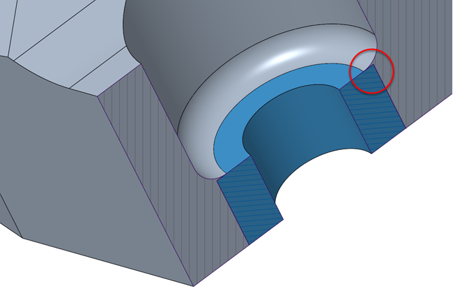
In this image, the top surface of the blue cylinder (preserved geometry) does not match with the gray fillet (starting geometry). This leads to reconstruction failure.
|
In this image, the top surface of the blue cylinder (preserved geometry) matches with the gray fillet (starting geometry). With this change, the reconstruction failure is avoided.
|
• Draft the preserved geometry to retain its shape during draft reconstruction. The draft angle of the preserved geometry should be equal to the draft angle defined for the Parting Line design constraint. For details, see Design Criteria.
Consider an example where the preserved geometry is not drafted.
 |
 |
|
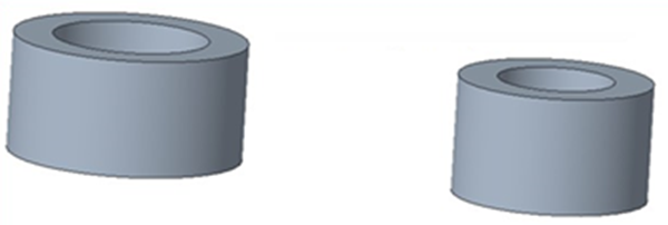
In this image, the preserved geometry is not drafted.
|
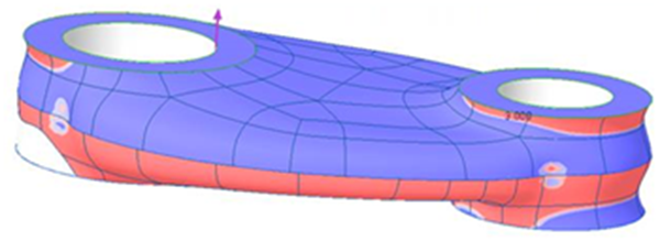
In this image, the draft reconstruction result is not accurate.
|
Consider an example where the preserved geometry is drafted.
 |
 |
|
In this image, the preserved geometry is drafted by an angle that matches with the draft angle defined for the Parting Line constraint.
|
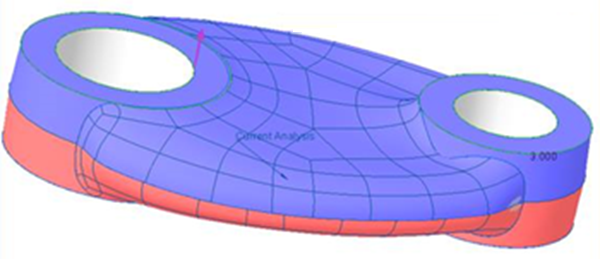
In this image, the draft reconstruction result is more accurate and the shape of the preserved geometry is retained.
|
• Specify the size of the element such that it is smaller than the thickness of the smallest feature in the model, such as sharp edges or thin layers.
Consider the following equation:
(Minimum size of the element) X 3 = (Minimum thickness of the smallest feature)
The size of the element is the value specified in the Min. element size box when you define optimization settings. For details, see Define Optimization Settings.
|
|
Smaller value of the element size increases the optimization time.
|
Consider the following image:
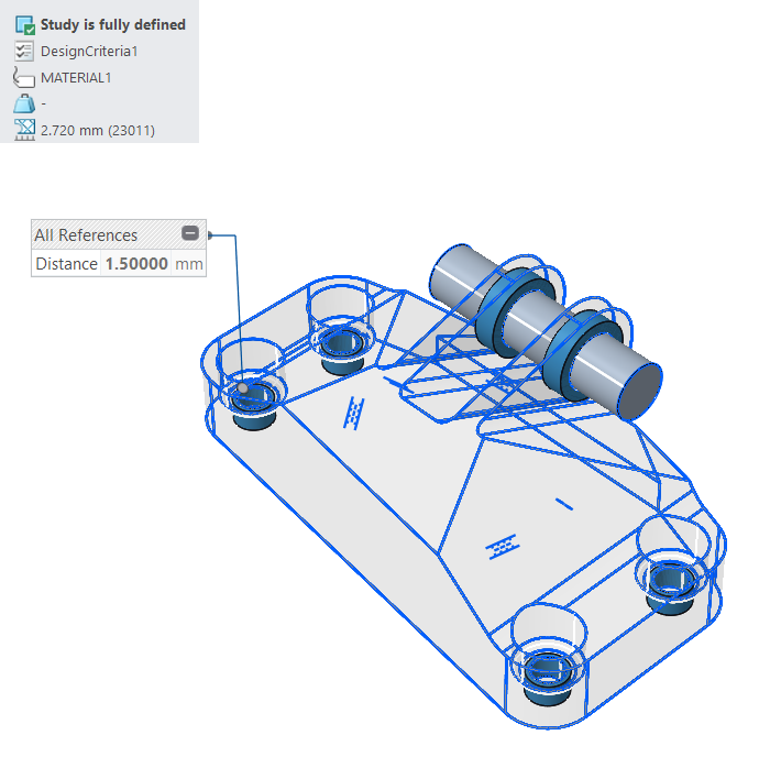 |
|
In this image, the element size (2.720 mm) is bigger than the minimum thickness of the cylinder (1.500 mm). This leads to reconstruction failure.
Make the element size lesser than 0.5 mm to avoid reconstruction failure.
|
• Correctly specify the unit for the size of the element. It should be the same as the unit of the model. For details, see Define Optimization Settings.
• Start with the  basic Resolution level for reconstruction. After successful reconstruction, select
  ,
,  , or
, or  for finer reconstruction results. If the finer results fail, use the basic level. It is still usable. For details, see Generate Design.
basic Resolution level for reconstruction. After successful reconstruction, select , , or for finer reconstruction results. If the finer results fail, use the basic level. It is still usable. For details, see Generate Design.As you increase the Resolution level, the time for geometry reconstruction increases. |
Consider the following images:
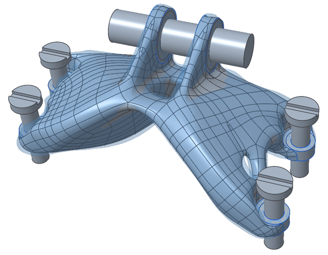 | 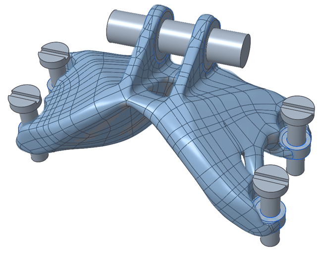 |
Result with the basic Resolution level. | Result with the Resolution level. |