Designating Connectors
Designating Components as Connectors
An assembly component must be designated as a connector before you use it as a connector. This makes the component eligible to carry pin and entry port information for starting and ending cables.
If you are using a logical reference from a Diagramming file, you can use the model_name diagram connector parameter to automatically designate specific components as connectors. After the part is designated, you can route wires or cables to it.
Autodesignating Components as Connectors
If the Cabling assembly has a logical reference to a diagram file or an XML file, you can automatically designate a component in the assembly as a connector. Automatic designation of a component as a connector is possible only when the corresponding connector in the diagram file or the XML file has the <model_name nnn> parameter associated with it. In this parameter, nnn is the model name of the 3D part in the Cabling assembly that you want to represent as the connector.
If you have not set the model_name parameter in your logical reference, you can still use the Auto Designator dialog box to select and match assembly components to connectors from the logical reference.
In an XML file, the assembly can have a group-block-port structure instead of a group-port structure. A group-block-port structure has subconnectors with ports within a parent connector with ports.
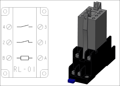
An assembly with a group-port structure is shown in the following figure:
An assembly with a group-block-port structure with L1 and L2 as subconnectors and L3 as parent connector is shown in the following figure:
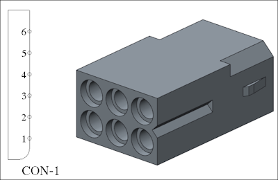
L1 has two ports named P1 and P2. L2 has two ports named P3 and P4. L3 has two ports named P5 and P6.
If you want to reassign the ports or pins of subconnectors to their parent connector and remove the subconnectors, use the Collapse option.
Subconnectors
Cabling also supports the concept of subconnectors. An example of subconnectors would be the ports in a PC case. The logical reference refers to the case as a connector and uses a node or pin for each port.
In a 3D assembly, the case is referred to as a connector and the parts assembled to the case representing the ports are designated as subconnectors.
The coordinate systems for the entry ports must be defined in the part before the part is designated as a connector in the Cabling mode. |
You can change the designation of a connector by designating it again or by modifying it. When you undesignate a connector, you must strip it of all connector data. Use Undesignate and Designate to replace all information in the connector parameters.
To Autodesignate Connectors
1. Click the arrow next to Auto Designate and click  Auto Designate. The Auto Designator dialog box opens.
Auto Designate. The Auto Designator dialog box opens.2. Match a listed connector with a selected 3D component.
3. If required, click Collapse to reassign pins from the subconnectors to the parent connector and remove the subconnectors.
Collapse is enabled only if none of the subconnectors of a parent connector have been designated. Cabling retains the previous action on the Collapse option. For example, if you have reassigned the pins from the subconnectors to the parent connector and removed the subconnectors using the Collapse option, then the next time you read in the logical reference, the logical reference for that connector is automatically collapsed. If you have changed your assembly and no longer want the automatic collapsing, you must undesignate the connector and read in the logical reference again. |
4. After matching a component with a diagram connector, use the editing tools for parameters and entry ports from the Auto Designator dialog box.
5. To assemble a missing component, click Assemble. The Component tab opens. Mention the Model_Name in the logical data, assemble the component and click  .
.
.Once assembled, the model is auto-designated. |
6. To match the components manually, click the Allow Mismatch check box.
Do you want to remove the hierarchy of subconnectors?If you click Yes, the pins from the subconnectors are reassigned to the parent connector and the subconnectors are removed. If you click No, the parent connector and the subconnectors are retained. |
To Manually Designate a Component as a Connector
1. Click the arrow next to Auto Designate.
Auto Designate.2. Click Designate.
3. Select the part or subassembly geometry that you want to represent or designate as a connector. The DES CONN menu appears.
4. Click From Logical to select a component from the components defined in the logical reference diagram.
or
Click Enter Name. You are prompted for a filename (.con) to read connector parameters from. At the prompt, type the name and press ENTER. If you do not specify a filename, the connector is defined using the default values. When the connection is defined, you can modify parameters or entry ports.
Specify the entry ports, that is, the coordinate systems where cables enter the connector.
After the part is designated, you can route wires or cables to it.
If you select a component that is logically referenced from a Diagramming file, components are automatically designated as connectors. |
To Undesignate a Connector
1. Click Undesignate.
2. Select the connector or splice. The component is no longer designated as a connector.