Exercise—Adding Full, Half, and Local Cross Sections
In this exercise, you learn how to add full cross section, half cross section, and local cross section to a drawing view.
Click here to download models for the exercises related to cross sections. Save the compressed folder detail_cross-section_models.zip to your computer and extract the folders.
Workflow
1. Open the model.
2. Create a projection view.
3. Set the view display.
4. Add a cross section to the view.
5. Do one of the following:
◦ Add a full cross section.
◦ Add a half cross section.
◦ Add a local cross section.
Open the Model
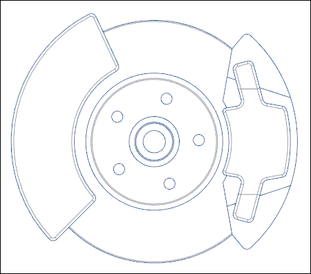
Set modified_actuator as the Working Directory and open modified_actuator.drw. The general view of the model appears.
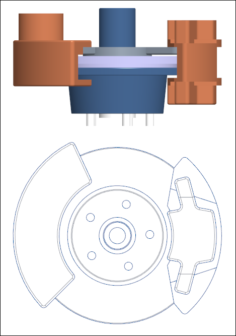
Create a Projection View
1. Click Projection View.
2. Click above the general view in the graphics window. A projection view is placed.
Set the View Display
1. Double-click the projection view. The Drawing View dialog box opens.
2. Under Categories, click View Display.
3. In the Display style list, select No Hidden.
4. In the Tangent edges display style list, select Dimmed.
5. Click Apply. The display of the projection view is set.
Add a Cross Section to the View
1. Under Categories, click Sections.
2. Under Section options, select 2D cross-section.
3. Do one of the following:
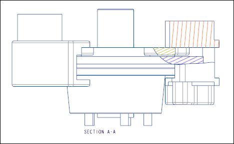
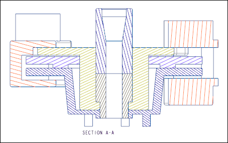
Add a Full Cross Section
1. Click  .
.
.2. In the Name list, select A.
3. In the Sectioned Area list, select Full.
4. Click > . The full cross section is added.
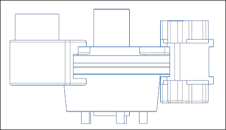
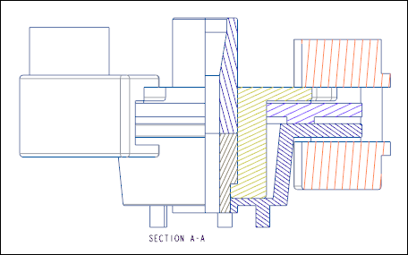
Add a Half Cross Section
1. Click .
.2. In the Name list, select A.
3. In the Sectioned Area list, select Half.
4. In the graphics toolbar, click  Datum Display Filters and select the
  Plane Display check box, if not already selected.
Datum Display Filters and select the Plane Display check box, if not already selected.5. In the Drawing View dialog box, click in the Reference box.
6. Select plane ADTM4 in the graphics window or on the Model Tree. An arrow pointing to left appears.
1. Plane
7. In the graphics toolbar, click Datum Display Filters and clear the Plane Display check box.
Datum Display Filters and clear the Plane Display check box.8. In the Drawing View dialog box, click in the Boundary box.
9. Click on the right side of the arrow in the graphics area. The arrow flips its direction.
1. Arrow
10. In the Drawing View dialog box, click > . The half cross section is added.
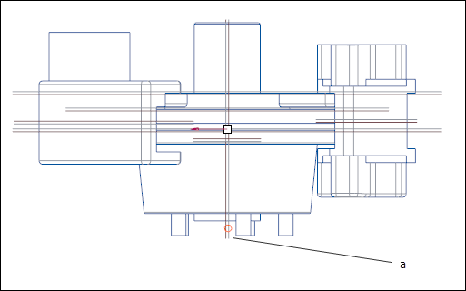
Add a Local Cross Section
1. Click .
.2. In the Name list, select A.
3. In the Sectioned Area list, select Local.
4. Click in the References box.
5. Select a point in the graphics area.
1. Point
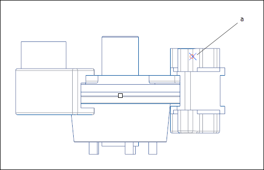
6. Create a spline around the selected point and middle-click when the spline is complete.

1. Spline
7. In the Drawing View dialog box, click > . The local cross section is added.