Working with Rough and Rest Rough Parameters
Watch the video that shows you how to work with Rough and Rest Rough parameters. This tutorial is a step-by-step guide on how to create HSM Rough and Rest Rough sequences.
Working with Scan and Cut Type Parameters
1. Open the MFG0001.ASM assembly.
2. On the Model Tree, click the sequence CONSTANT_LOAD and then click  to edit the definition. The HSM Rough tab opens.
to edit the definition. The HSM Rough tab opens.3. Click  and select SF30_R1_ISO50 tool with cutter diameter of 30 mm.
and select SF30_R1_ISO50 tool with cutter diameter of 30 mm.4. On the References tab, click the Mill window collector and on the Model Tree, select Mill Window 1.
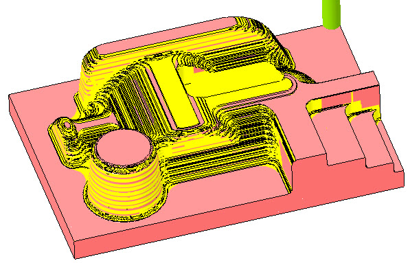
5. On the Parameters tab, the parameters are populated automatically, based on the tool diameter. To optimize the toolpath, set values as shown for the following parameters:
◦ SCAN_TYPE = CONSTANT_LOAD
◦ CUT_TYPE = CLIMB
◦ ROUGH_OPTION = ROUGH_ONLY
◦ ROUGH_STOCK_ALLOW = 1
◦ BOTTOM_STOCK_ALLOW = 1
◦ MAX_STEP_DEPTH = 5
◦ CLOSED_AREA_ENTRY = HELICAL
◦ RAMP_ANGLE = 15
◦ PULLOUT_DIST = 5
◦ HELICAL_DIAMETER_PERC = 50
6. Click the arrow next to  and then click
  . The Material Removal tab opens.
and then click . The Material Removal tab opens.7. Click to open the Play Simulation dialog box.
to open the Play Simulation dialog box.8. Click  to play simulation.
to play simulation.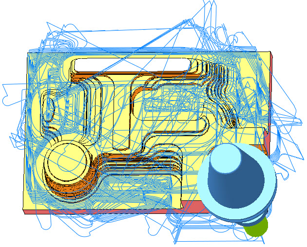
9. On the Material Removal tab, click  and then on the HSM Rough tab, click OK to complete the sequence.
and then on the HSM Rough tab, click OK to complete the sequence.10. On the Model Tree, click the sequence TYPE_SPIRAL and then click to edit the definition. The HSM Rough tab opens.
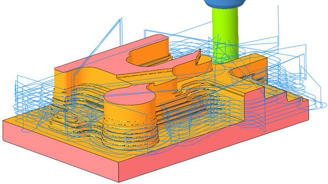
to edit the definition. The HSM Rough tab opens.11. On the Parameters tab, set values as shown for the following parameters and then repeat steps 6–9:
◦ SCAN_TYPE = TYPE_SPIRAL
◦ CUT_TYPE = UPCUT
◦ ROUGH_OPTION = ROUGH_ONLY
◦ CLOSED_AREA_ENTRY = AUTOMATIC
◦ PULLOUT_DIST = 5
12. On the Model Tree, click the sequence TYPE_1 and then click to edit the definition. The HSM Rough tab opens.
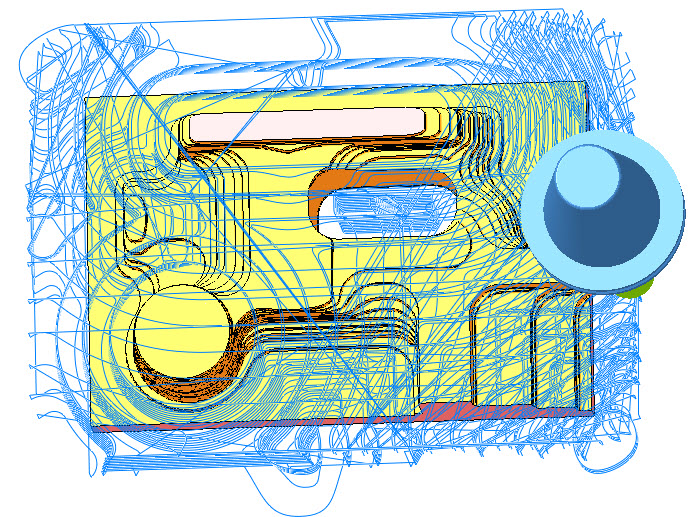
to edit the definition. The HSM Rough tab opens.13. On the Parameters tab, set values as shown for the following parameters and then repeat steps 6–9:
◦ SCAN_TYPE = TYPE_1
◦ CUT_TYPE = ZIG_ZAG
◦ ROUGH_OPTION = ROUGH_AND_PROF
◦ CLOSED_AREA_ENTRY = RADIAL
◦ PULLOUT_DIST = 5
Working with Other Roughing Parameters
1. On the Model Tree, click the sequence CONSTANT_LOAD and then click to edit the definition. The HSM Rough tab opens.
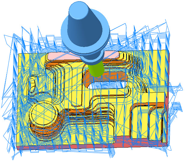
to edit the definition. The HSM Rough tab opens.2. On the Parameters tab, the parameters are populated automatically, based on the tool diameter. To optimize the toolpath, set values as shown for the following parameters:
◦ NUMBER_INTERMEDIATE_SLICES = 2
◦ INTERMEDIATE_SLICE_ADJUST = AFTER
◦ MAX_STEP_DEPTH = 15
3. Click the arrow next to and then click . The Material Removal tab opens.
and then click . The Material Removal tab opens.4. Click to open the Play Simulation dialog box.
to open the Play Simulation dialog box.5. Click to play simulation.
to play simulation.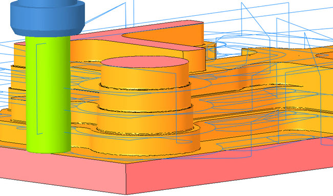
6. On the Material Removal tab, click .
.7. On the Parameters tab, set values as shown for the following parameters and then repeat steps 3–6:
◦ NUMBER_INTERMEDIATE_SLICES = 0
◦ START_HEIGHT = 60
◦ END_HEIGHT = 25
◦ MAX_STEP_DEPTH = 5
8. On the Parameters tab, set values as shown for the following parameters and then repeat steps 3–6:
◦ ALLOW_ENTRY_OUTSIDE = NO
◦ RAMP_ANGLE = 5
◦ CLOSED_AREA_ENTRY = HELICAL
◦ HELICAL_DIAMETER_PERC = 30
9. Click OK to complete the sequence.
10. On the Model Tree, click Mill window 1 and then click to edit the definition. The Mill Window tab opens.
to edit the definition. The Mill Window tab opens.11. On the Options tab, select Inside window contour and click OK.
12. On the Model Tree, click the sequence CONSTANT_LOAD and then click to open the PLAY PATH dialog box.
to open the PLAY PATH dialog box.13. Click to play simulation.
to play simulation.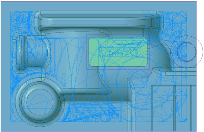
14. On the Model Tree, click Mill window 1 and then click to edit the definition. The Mill Window tab opens.
to edit the definition. The Mill Window tab opens.15. On the Options tab, select Outside window contour and click OK.
16. On the Model Tree, click the sequence CONSTANT_LOAD and then click to open the PLAY PATH dialog box.
to open the PLAY PATH dialog box.17. Click to play simulation.
to play simulation.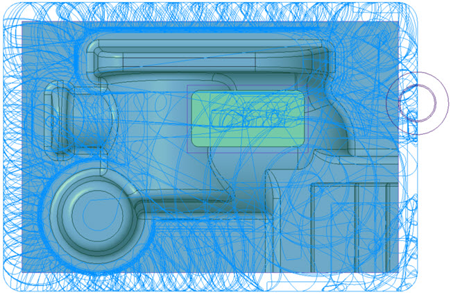
18. On the Model Tree, click the sequence TYPE_SPIRAL and then click to edit the definition. The HSM Rough tab opens.
to edit the definition. The HSM Rough tab opens.19. On the Parameters tab, set values as shown for the following parameters and then repeat steps 3–6:
◦ STEP_OVER = 28
◦ REMOVE_CORNER_PEGS = YES
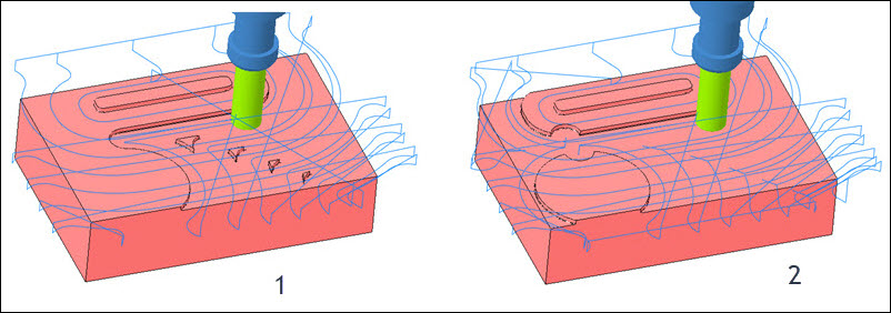
1. REMOVE_CORNER_PEGS is set to NO.
2. REMOVE_CORNER_PEGS is set to YES.
20. On the References tab, click the Mill window collector and on the Model Tree, select Mill Window 3.
21. On the Parameters tab, set values as shown for the following parameter and then repeat steps 3–6:
◦ BOTTOM_STOCK_ALLOW = 0
◦ MAX_STEP_DEPTH = 8
◦ MACHINE_FLATLANDS = NO
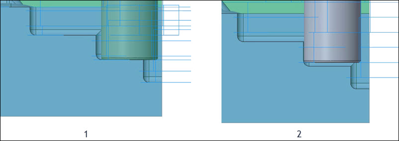
1. MACHINE_FLATLANDS is set to YES.
2. MACHINE_FLATLANDS is set to NO.
22. On the Parameters tab, set values as shown for the following parameters and then repeat steps 3–6:
◦ MACHINE_FLATLANDS = YES
◦ MINIMUM_WIDTH = 8
◦ MAX_STEP_DEPTH = 5
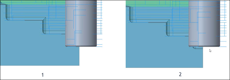
1. MINIMUM_WIDTH is set to 1.
2. MINIMUM_WIDTH is set to 8. When the MINIMUM_WIDTH is set to 8 the last pass is omitted.
Working with Rest Roughing Options
In the following steps, you will work with parameters that are unique to Rest Roughing.
1. On the Model Tree, click the sequence RE_ROUGH_PREV_TOOL and then click to edit the definition. The HSM Rest Rough tab opens.
to edit the definition. The HSM Rest Rough tab opens.2. Click and select SF16_R1_ISO50 tool with a cutter diameter of 16 mm.
and select SF16_R1_ISO50 tool with a cutter diameter of 16 mm.On the References tab, the Reference Cutting Tool automatically collects the previously used tool SF30_R1_ISO50.
3. On the Parameters tab, the parameters are populated automatically, based on the tool diameter. To optimize the toolpath, set values as shown for the following parameters:
◦ STEP_OVER = 8
◦ MAX_STEP_DEPTH = 5
◦ ROUGH_STOCK_ALLOW = 1
◦ BOTTOM_STOCK_ALLOW = 1
◦ PREVIOUS_ROUGH_STOCK_ALLOW = 1
◦ PREVIOUS_BOTTOM_STOCK_ALLOW = 1
4. Click arrow next to and then click . The Material Removal tab opens.
and then click . The Material Removal tab opens.5. On the Material Removal tab, click > . The Load stock dialog box opens.
6. Select rough.bin and click Open.
7. Click to open the Play Simulation dialog box.
to open the Play Simulation dialog box.8. Click to play simulation.
to play simulation.
When you use a previous tool to calculate the tool path, limitations, such as tool length and holder geometry affect the rest roughing sequence. In such scenarios, you can generate more accurate tool paths by using the previous stock. |
9. On the Material Removal tab, click and then on the HSM Rest Rough tab, click OK.
and then on the HSM Rest Rough tab, click OK.10. On the Model Tree, click the sequence RE_ROUGH_PREV_STOCK and then click to edit the definition. The HSM Rest Rough tab opens.
to edit the definition. The HSM Rest Rough tab opens.11. On the References tab, click the Mill window collector and on the Model Tree, select Mill Window 1.
12. On the References tab, in the Rough Stock File collector, click  to import the rough stock file. The Open dialog box opens.
to import the rough stock file. The Open dialog box opens.13. Select rough.stl and click Open.
14. On the Parameters tab
, click  . The Select Step dialog box opens. The RE_ROUGH_PREV_TOOL sequence is selected.
. The Select Step dialog box opens. The RE_ROUGH_PREV_TOOL sequence is selected.15. Click OK to copy parameters and repeat steps 4–9.