Meshing
Binary Tree Mesh is the proprietary meshing technique you can use to create a mesh inside, outside, or both inside and outside any water tight geometry defined by a CAD surface. The technique starts with a single hexagonal parent cell encompassing the geometries of interest. The meshing then sequentially subdivides or cuts successive generations of cells until you get the desired resolution and representation of the original surface.
The binary tree mesher provides an accurate reproduction of the original geometry but preserves the following:
• Edges based on the critical edge angle
• Curvature based on the curvature resolution
The Binary Tree Mesher provides high quality grids for numerical efficiency and accuracy. The binary tree mesher is efficient in creating a mesh for most complex arbitrary shapes, with the exception of geometries that have a high aspect ratio, such as 10,000:1.
To mesh the model for the created fluid domain, select Domains in the Flow Analysis Tree. The meshing options are listed below:
• Surface Tessellation—Controls resolution of the surfaces in the selected domain through the tessellations. This is determined by providing values for the Chord Heights and Angle Controls. The default value for Chord Heights is 0.001 and default value for Angle Controls is 0.100.
• Mesh Generation—Contains options available for a selected fluid domain under Domains.
In Setup Options select Normal Mode or Advanced Mode.
◦ Normal Mode—Limits the options that are available. Setup should be easier and less error prone.
◦ Advanced Mode—All options are available.
Normal Mode Options
|
Option
|
Description
|
Values
|
|---|---|---|
|
Create/Replace Mesh
|
New mesh or store build mesh.
|
New Mesh, or Store Build Mesh
|
|
Mesh Name
|
Provide a mesh name.
|
|
|
Mesh Location
|
Sets the location of the mesh.
|
Interior Volumes, Exterior Volumes, or All Volumes
|
|
Cell Size Specification
|
Determines whether to use relative or absolute length scales for meshing parameters requiring length, such as those listed below:
• Maximum Cell Size
• Minimum Cell Size
• Cell Size on Surfaces
|
Relative to All CAD Surfaces, Relative to Selected CAD Surfaces, or Absolute
|
|
Critical Edge Angle
|
Sets the accuracy with which the mesher resolves edges in CAD Surfaces. The lesser the critical edge angle, the better is the resolution of the edges.
|
Default value is 30
|
|
Curvature Resolution
|
Sets the accuracy with which the mesher resolves curves in CAD Surfaces.
|
Default value is 35.0
|
|
Maximum Cell Size
|
Sets the size of the cells throughout a mesh volume. It is specified in terms of Relative to All CAD Surfaces, Relative to Selected CAD Surfaces, or Absolute. No cell in the volume can have a cell side larger than the Maximum Cell Size.
|
Default value is 0.02
|
|
Minimum Cell Size
|
Limits how small cells can attempt to resolve the geometry. The minimum cell size is specified in terms of Relative Size or also applies to all the cells in a volume. No cell in the volume can have a cell side smaller than the Minimum Cell Size.
|
Default value is 0.0007
|
|
Cell Size on Surfaces
|
Controls the size of the cells for all surfaces of a mesh volume. Cell Size on Surfaces is specified in terms of Relative to All CAD Surfaces, Relative to Selected CAD Surfaces, or Absolute. No cell on the surface can have a cell side larger than the value of Cell Size on Surfaces.
|
Default value is 0.01
|
|
Create a Refinement Zone
|
Controls the size of the mesh cells within defined zones of a volume. You can create any number of refinement zones. Cells within a zone are subsequently based on Cell Size, which is similar in function to Maximum Cell Size.
When you create a refinement zone, you must set the desired dimensions of the zone geometry and the cell size prior to the meshing operation. The specified value of cell size is applied inside the zone being meshed. A new zone is created each time you click Box Zone Refinement, Cylindrical Zone Refinement or User Defined Refinement. You can remove the zone by selecting Remove This Zone in the Refine Zone Options list.
|
No, Box Zone Refinement, Cylindrical Zone Refinement, or User Defined Refinement
|
|
Cell Size on Boundaries
|
Controls the size of the boundary cells generated next to an individual CAD Surface. No boundary cell at the selected surface can have a cell size larger than the corresponding Cell Size on Boundaries. It is a length scale specified in terms of Relative Size or Absolute Size. The User Input value of the Cell Size on boundaries is applied only for the selected surface. Smaller values will provide higher resolution.
|
|
|
Min. Cell Refinement on Boundaries
|
Limits minimum cell size while resolving a CAD geometry using the General Mesher. Also used to provide local refinement on CAD Surfaces that present small features such as tight gaps, sharp curvature etc. They define the number of levels the Minimum Cell Size is decreased by. Three different levels of limiting are offered under Min. Cell Refinement on Boundaries: Refine One Level (half), Refine Two Levels (four times), and Refine Three Levels (eight times).
|
Advanced Mode Options
|
Option
|
Description
|
Values
|
||
|---|---|---|---|---|
|
Bounding Box Margins
|
Controls how the bounding box is constructed. The bounding box is an imaginary box placed around a volume to be meshed. The bounding box is the starting point for subsequent cell division by the Binary Tree meshing capability.
|
Automatic,Uniform, Nonuniform, or Diagonal Positions
|
||
|
Cell Size near Critical Edges
|
Controls the size of the cells near a critical edge. This is the edge resolved by the mesh based on the Critical Edge Angle. It is a length scale specified in terms of Relative to All CAD Surfaces, Relative to Selected CAD Surfaces, or Absolute. No interior cell adjacent to critical edge can have a cell side larger than value for Cell Size near Critical Edges.
|
Default value is 0.02
|
||
|
Cell Size near Critical Points
|
Controls the size of the interior cells near a critical point. This is a point where two critical edges connect. Cell Size near Critical Points is specified in terms of Relative to All CAD Surfaces, Relative to Selected CAD Surfaces, or Absolute. No interior cell near a critical point can have a cell side larger than the value for Cell Size near Critical Edges.
|
Default value is 0.02
|
||
|
Cell Size on Surface Near Edges
|
Controls the size of the boundary cells near the critical edges. Cell Size on Surface Near Edges is specified in terms of Relative to All CAD Surfaces, Relative to Selected CAD Surfaces, Absolute. No boundary cells adjacent to a critical edge can have a cell side larger than the Cell Size on Surface Near Edges.
|
Default value is 0.02
|
||
|
Cell Size on Edge Near Points
|
Controls the size of the edges near a critical point. This is a point where two critical edges connect. Cell Size on Edge Near Points is specified in terms of Relative to All CAD Surfaces, Relative to Selected CAD Surfaces, Absolute. No edge adjacent to a critical point can have a cell side larger than the value for Cell Size on Edge Near Points.
|
Default value is 0.02
|
||
|
Tree Orientation X Axis
|
Sets the orientation of the Bounding Box. The new orientation of the X-Axis for the bounding box is set after you provide the X, Y, and Z components of a vector.
|
You provide the X, Y, and Z components of a vector.
|
||
|
Tree Orientation Y Axis
|
Sets the orientation of the Bounding Box. The new orientation of the Y-Axis of the bounding box is set after you provide the X, Y, and Z components of a vector.
|
You provide the X, Y, and Z components of a vector.
|
||
|
Node Merge Tolerance(Distance)
|
Sets the tolerance at which two nodes are merged into a single point. It is specified in terms of Relative to All CAD Surfaces, Relative to Selected CAD Surfaces, Absolute.
|
Default value is 0.000070
|
||
|
Refine Cells next to Boundary Cells
|
Refines the cells in the transition from one Boundary to the next so that they are of the same order in size. Refine Cells next to Boundary Cells is specified in terms of Relative to All CAD Surfaces, Relative to Selected CAD Surfaces, Absolute.
|
No or Yes
|
||
|
Parallel Cell Aspect Ratio
|
Controls the aspect ratio of the cells. Parallel Cell Aspect Ratio controls mesh density near the control volume surfaces.
|
A value between 1 and 8. Default value is 2.
|
||
|
Maximum Cell Proportion
|
Controls the mesh and limits the aspect ratio of the cells.
|
You provide the X, Y, and Z components of a vector.
|
||
|
Sub-feature Options
|
Controls the grouping subfeatures. When you select Combined with Patches, the Sub-feature Options attaches the subfeatures to the nearest surface. Separate Patches and Separate Volumes show the subfeatures as a separate Boundary and Volume.
|
Combined with Patches, Separate Patches, or Separate Volumes
|
||
|
Volume Name by Surface Prefix
|
Activates the naming of volumes based on the prefix of the CAD Surface names.
|
No or Yes
|
||
|
Volume Options
|
Controls the retainment of volumes during meshing. Multiple Volumes retains all volumes and is the default option.
|
Multiple Volumes, Biggest Volume, or Single Volume
|
||
|
Volume Order by Size
|
Orders volumes based on mesh size, in the Flow Analysis Tree.
|
No or Yes
|
Interface Creation
An interface is an internal boundary of a model. It is located within a volume or connects two separate volumes. It connects the mesh cells on either side of the interface.
There are two types of interfaces:
• Internal Interface—Automatically created during mesh generation when cells are on either side of a CAD Surface. Internal interfaces are created in two ways:
◦ When an isolated CAD surface is inside an enclosed volume such as, a plate inside a cube.
◦ When the CAD surfaces defining an enclosed volume are inside another bigger volume, such as, a sphere inside a cube. The general mesher creates two volumes where the surface of the sphere is an internal interface between the two volumes.
• Mismatched Grid Interface (MGI)—Connect two disconnected volumes so that flow passes between them. To create the MGIs, click  Connect Selected Boundaries via MGI. The MGIs appear under Boundary Conditions in the Flow Analysis Tree. The following options are specified for a selected MGI set in the Properties panel:
Connect Selected Boundaries via MGI. The MGIs appear under Boundary Conditions in the Flow Analysis Tree. The following options are specified for a selected MGI set in the Properties panel:◦ Projection Method—There are three projection methods, Automatic, Planar, and Cylindrical:
▪ Automatic—Automatically selects the projection surface for connecting boundaries.
▪ Planar—Uses a plane as the projection surface for connecting boundaries. There are two Planar options:
Position—Determines the position of the planar projection surface used in the planar method for connecting boundaries.
Boundary Normal—Determines the orientation of the planar projection surface used in the planar method for connecting boundaries. This is relative to the mismatched grid interface projection surface. Be careful not to confuse Boundary Normal with the local normals of the boundary faces.
▪ Cylindrical—Uses a cylinder as the projection surface for connecting boundaries.
Cylindrical Radius—Determines the radius of the cylindrical projection surface used in the cylindrical method for connecting boundaries.
Cylindrical Center—Determines the position of the cylindrical projection surface used in the cylindrical method for connecting boundaries.
Axis Vector—Determines the orientation of the cylindrical projection surface used in the cylindrical method for connecting boundaries.
◦ Projection Tolerance—Maximum distance between the local boundary face and the projection surface. To connect through mismatched grid interface, the two boundaries should be closer than the projection tolerance. Any boundary faces farther from the projection surface than this tolerance, are not connected through the mismatched grid interface.
◦ Normal Tolerance—The angle between two boundaries must be less than the normal tolerance for them to connect through mismatched grid interface.
◦ Face Distance Tolerance—The distance between any two cell faces of two boundaries must be less than the face distance tolerance for them to connect through mismatched grid interface.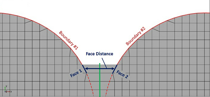
◦ Face Normal Tolerance—The angle between the normal of any two cell faces of opposing boundaries must be less than the face normal tolerance for them to connect through mismatched grid interface.
The projection surface determined by the projection method is only used for mapping the boundaries. It does not have to lie between the boundaries to create the connection. |

Volume Remesh
Mesh movement is the time-dependent change of volume mesh to solve transient flows. Mesh movement is performed in the Properties panel by Volume Remesh. To specify the method of mesh movement, follow the steps listed below:
1. In the Flow Analysis Tree, under Domains select the volume.
2. In the Properties panel, Model tab, click Common.
3. Set Volume Remesh to Volume Remesh.
4. Select the method.
You can remesh a volume using one of methods below:
• Translation—Translates a selected volume and associated mesh. The motion is defined by a displacement or a velocity.
• Rotation—Rotates a selected volume and associated mesh as a function of time. The parameters associated with rotation are listed below:
◦ Rotational Direction—Determines the direction of rotation for the rotating volume. You can select Clockwise, Counter Clockwise, or Both Directions.
◦ Rotational Speed—Determines the magnitude (and in some cases direction) of the volume rotation. A negative value of rotational speed corresponds to an anticlockwise rotation when the Rotational Direction is set to Both Directions. This value is specified as rpm or expressions.
◦ Rotational Center—Specifies the rotational center for the rotating volume. This value is specified in terms of a coordinate lying on the rotational axis.
◦ Rotational Axis Vector—Specifies the rotational axis vector for the rotation of the volume. The values are the components of the rotational axis vector.
• Compression/Expansion—Deforms a volume based on a scale length and reference point. Scale length is the maximum length of the expanding or compressing volume. Compression/expansion motion stretches the shape of the selected volume uniformly in all three directions around a reference point.
• Composite Motion—Deforms a volume based on a reference point and one, two, or three direction points. This method stretches the shape of the selected volume using a reference point and one, two, or three tug points that stretch the {x,y,z} coordinate system as if elastic.
• By Dynamics—Deforms or moves a volume as a function of time based on motion defined using a selected dynamics module Translation (1 DOF) or Rotational (1 DOF).
• Radial Motion(Cylinder)—Deforms the annulus volume based on movement of inner cylinder with respect to stationary outer cylinder. The parameters associated with Radial Motion(Cylinder) are listed below:
◦ Displacement—Function {x,y,z} to displace the moving cylinder.
◦ Center of Cylinder—Center of the moving cylinder.
◦ Cylinder Axis Vector—Common axis of the moving and stationary cylinder.
◦ Radius of Moving Cylinder—Radius of the cylinder to move.
◦ Radius of Stationary Cylinder—Radius of the stationary (outer) cylinder.
◦ Minimum Gap—Minimum gap between the two cylinders.
• Expression—Deforms a volume based on user-defined expressions for the {x,y,z} coordinates. This moves the {x,y,z} coordinates of a selected volume and associated mesh as a function of time, based on expressions for each coordinate. The new coordinate positions are based on their original coordinates {x,y,z} which do not change during remeshing.
• External Grid File—Deformation of a volume is specified through external files. The {x,y,z} coordinates of a selected volume and associated mesh move as specified by an external grid file. The options associated with External Grid File are:
◦ Base Name—Base name of all the external files.
◦ Files Found—Number of files to be read.
◦ Header Lines—Number of lines preceding the {x,y,z} coordinates in the external file.
◦ Cyclic—Files are read repeatedly for each cycle if you select Yes.
The name of the external grid file must be in the format of <BaseName><number>. The file contains the coordinates with the header line indicating the number of points in the corresponding file. |