Beam Idealizations—Creo Ansys Simulation
A beam is a one dimensional idealization that is used to model 3D structures in which the length is much greater than the other two dimensions. You can create a beam idealization and apply it selected curves by specifying the shape and position of the beam cross-section, and the location and orientation of the beam with respect to the curve where the beam load is applied. The degrees of freedom at the beam ends can be defined independently as “beam releases” and are applied to either the end of a beam, or to the vertex or junction at which multiple beams meet.
Specifying the Beam Orientation
To specify the beam orientation you define the XY plane for the beam action coordinate system, where the X axis is always along the (tangent to the ) beam axis. When you specify the orientation the XY plane is defined, and the Z axis is defined perpendicular to it using the right hand rule, to fully define the beam action coordinate system. The YZ plane determines the plane of the beam section coordinate system.
For example, in the following example a square beam has its X- axis parallel to the model coordinate system. The following examples illustrate the selection of Y direction using the three different options:
• Define by Vector—Here the Y-direction is defined by vector component values (010) which means the beam Y- axis is parallel to the model Y- axis.
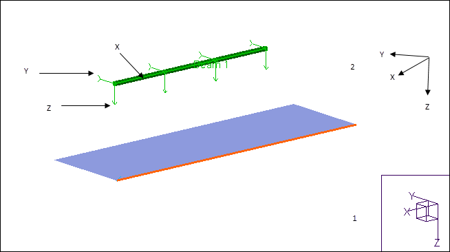
1. Model coordinate system
2. Beam Action Coordinate system
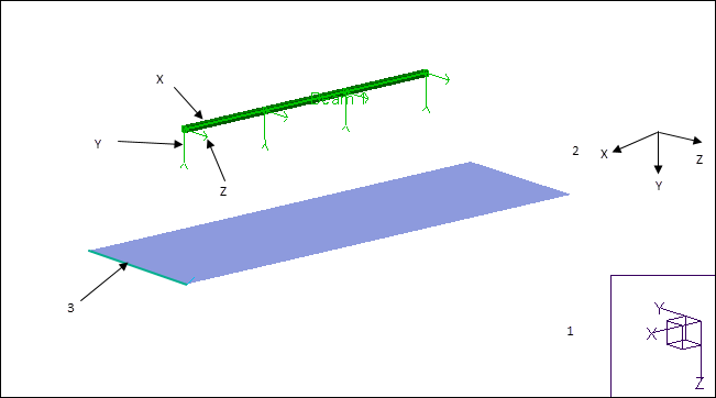
• Y-direction by point — Select a vertex or a datum point in the model that does not lie along the beam axis (X- axis) or parallel to it.

1. Model coordinate system
2. Beam Action Coordinate system
3. Point used to define Y- direction
• Y-direction by Axis—Select an edge or curve to define the Y-direction
1. Model Coordinate System
2. Beam Action Coordinate System
3. Edge used to define Y- direction
To Define a Beam
1. Click >  Beam. The Beam Definition dialog box opens.
Beam. The Beam Definition dialog box opens.2. Select edges or curves as references on which to define beams. If you select multiple references they must be all of the same type only. Your selections are displayed in the References collector.
3. Select a previously defined beam section from the Beam Section list or select Create new to create a new beam section.
4. To specify the orientation of the beam action coordinate system specify the Y- direction of the beam using one of the following methods:
◦ Y-Direction by Point—Select a vertex or a datum point on the model to define the Y-direction. The vertex cannot be along the beam axis or parallel to the beam axis.
◦ Y-Direction by Axis—Select an edge or curve to define the Y-direction.
◦ Y-Direction by Vector—Select vector component values to define the Y direction. The vector value must not be (0,0,0) and the vector must not coincide with the X direction or be perpendicular to it anywhere along the curve.
5. Optionally, click + next to Origin to specify the location and orientation of the beam cross section with respect to the beam action coordinate system. Select one of the following options:
◦ Centroid—The beam curve intersects the beam section at the centroid. Specify the Angle to rotate of the beam section about the beam curve.
◦ Shear Center—The beam curve intersects the beam section at the Shear Center. Specify the Angle to rotate the beam section about the beam curve.
◦ Shape Origin—Specify the location where the where the beam curve intersects the beam section by Dy and Dz offsets from the shape origin
6. Optionally, Specify the Angle to rotate the beam section about the beam curve. (RH rule positive)
7. Select a material from the model on the Material list or click More to select a material from the Material Library or create a new material.
8. Click OK to create the beam and to save it.