User Interface and Workflow
Starting the Application
After opening a part or assembly model to which you intend to apply GD&T, startup GD&T Advisor by selecting the GD&T Advisor button on the Applications ribbon. Note that access to GD&T Advisor for assemblies requires the GDT_ENTERPRISE license option.
Once the application has been started within a Creo modeling session, it will continue to run until you either exit Creo or select Close in the GD&T Advisor ribbon. Closing the application releases the GD&T Advisor license.
Model Update
The application runs through the Model Update process under the following conditions:
• When GD&T Advisor starts.
• When GD&T Advisor is running and the CAD model is regenerated.
• When the Update button is selected from GD&T Advisor ribbon.
The Model Update process includes the following steps:
1. Model Cleanup — Due to a variety of conditions, annotations in the model may become 'misplaced', such that they cannot be shown in the model. One way this could happen if there is a change made to the CAD model such that an annotation is no longer compatible with the annotation plane. For example, the diameter of a shaft must be placed on a plane that is either through or normal to the shaft axis. If the diameter dimension is placed on an annotation plane that is neither of those, the diameter dimension cannot be displayed. In some cases, not only are these annotations not displayed but they are sometimes not even listed in the model tree. In order to ensure that the model is 'clean', when you start up GD&T Advisor, the application searches the model for misplaced annotations and automatically deletes any that are found.
2. Checks the Tolerancing Standard — The application reads the tolerancing standard and version from the CAD model properties and applies the applicable rule set based on the specified standard.
3. Checks for Unvalidated Annotations — The application searches the model for annotations created with native Creo annotations tools (i.e., not with GD&T Advisor). When starting the application on a part for the first time, you are presented with an option to either delete or validate these annotations, depending on the available license options (see Unvalidated Annotations for more information). When the CAD model already includes GD&T Advisor data, the application attempts to automatically validate all unvalidated annotations. Any annotations that cannot be validated are listed in the Manage Annotations.
4. Updates the GD&T Advisor Model Data — The application performs the following additional tasks:
◦ Updates all features and linked patterns (based on the current state of the CAD model).
◦ Checks all validated annotations and…
▪ Identifies mismatches between the annotations and the expected data
▪ Updates GD&T Advisor based on any valid changes made to the CAD annotations
◦ Runs all advisor tests and updates advisor messages.
User Interface
The picture below shows the various components of the GD&T Advisor user interface.
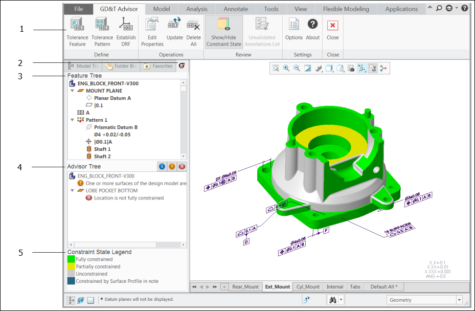
1. GD&T Advisor Ribbon
2. GD&T Advisor Navigator Tab
3. Feature Tree
4. Advisor Tree
5. Constraint State Legend
The GD&T Advisor Ribbon
The GD&T Advisor ribbon in Creo Parametric that contains the following buttons:
Button | Function | Description |
|---|---|---|
 | Tolerance Feature | Add a feature to the GD&T Advisor model and then applying tolerances to that feature. See Add Feature for more information. |
 | Tolerance Pattern | Add a pattern to the GD&T Advisor model and then applying tolerances to that pattern. See Add Pattern for more information. |
 | Establish DRF | Add a datum reference frame to the GD&T Advisor model. See Add DRF for more information. |
 | Edit Properties | Edit the properties of the GD&T Advisor model. See Edit Model Properties for more information. |
 | Update | Update the GD&T Advisor data, including changes made to the CAD model. |
 | Delete All | Delete all of the GD&T Advisor data from the CAD model and then close the application. |
 | Show/Hide Constraint State Display | Toggle the display mode of the CAD model. When the Constraint State Display is activated, the surfaces of the model are color-coded to indicate their constraint state. See Constraint State Display for more information. |
 | Manage Annotations | View lists of unvalidated and mismatched annotations. See Manage Annotationsfor more information. |
 | Options | View and/or edit the application options. See Application Options for more information. |
 | About GD&T Advisor | Opens a window with information about the application (e.g., version and license info). |
 | Close | Close the application. |
GD&T Advisor Navigator Tab
GD&T Advisor is very tightly integrated with Creo Parametric. When you first start the application, there is a new tab added to the Creo Navigator pane. The GD&T Advisor navigator pane displays two components of the user interface: the Feature Tree and the Advisor Tree.
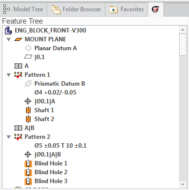
Feature Tree
The Feature Tree displays the contents of the GD&T Advisor model, including features, patterns, datum reference frames, dimensions, and geometric tolerances. The order of the Feature Tree reflects the precedence of the features in the model. Thus, datum features that are used to establish the predominant datum reference frame of the part should be the first features in the Feature Tree.
Feature Tree Objects
The Feature Tree contains various icons as described in the table below.
Icon | Meaning |
|---|---|
 | The active part or assembly |
 , etc. , etc. | A feature (see Feature Descriptions for a complete list of supported feature types) |
 | A pattern (see Pattern Descriptions for a complete list of supported pattern types) |
 , ,  , etc. , etc. | A datum plane or a datum axis. |
 | A datum reference frame (DRF). A DRF is always ordered to immediately follow the last referenced datum feature. |
 , etc. , etc. | A size dimension |
 , etc. , etc. | A geometric tolerance (see Geometric Controls (ASME), or Geometric Controls (ISO) for more information) |
In some cases, an object in the Feature Tree may be marked by a double dagger symbol (‡), indicating that it is a 'failed' object, or a single dagger symbol (†) indicating that it is dependent on a failed object. See the 'There are failed objects in the model' advisor message help page for more information.
Feature Tree Context Menu
When you right-click in the Feature Tree, a context menu will be displayed. The content of the menu depends on which object type is selected:
Selected Object Type | Menu Contents | Description |
|---|---|---|
Any | Options... | Edit the application options. See Application Options for more information. |
Expand All | Fully expand the feature tree. | |
Collapse All | Fully collapse the feature tree. | |
Part or Assembly | Edit Properties... | Edit the model properties. See Edit Model Properties for more information. |
Update | Update the GD&T Advisor data, including changes made to the CAD model. | |
Delete All | Delete all of the GD&T Advisor data from the CAD model and close the application. | |
Tolerance Feature | Add a feature to the GD&T Advisor model and then applying tolerances to that feature. | |
Tolerance Pattern | Add a pattern to the GD&T Advisor model and then applying tolerances to that pattern. | |
Establish DRF... | Add a datum reference frame to the model. | |
Feature | Rename | Rename the selected feature. |
Edit... | Open the dashboard to modify the feature properties. | |
Delete | Delete the feature. | |
Reorder | Reorder the selected feature(s) to a new location in the feature tree. | |
Set Datum... | Set the selected feature as a datum feature (only applicable for certain pattern members). | |
Pattern | Rename | Rename the selected pattern. |
Edit... | Open the dashboard to modify the feature properties. | |
Delete | Delete the pattern. You will be given the option to keep or delete the member features. | |
Reorder | Reorder the selected pattern to a new location in the feature tree. | |
Datum | Change Label | Change the label for the datum feature or datum from targets |
Delete | Delete the datum from the feature | |
DRF | Edit... | Modify the properties of the datum reference frame. |
Delete | Delete the datum reference frame. | |
Show Simultaneous Requirements | Identifies all simultaneous requirements associated with the DRF (not applicable to the ISO 1101 tolerancing standard) | |
Dimension | Edit Dimension... | Edit a dimension. When there are two dimensions shown together (e.g., diameter and depth), there is a sub-menu to select the specific dimension to edit. |
Geometric Tolerance | Edit... | Edit the value for the geometric tolerance. |
Advisor Tree
GD&T Advisor continuously monitors the model for potential problems.
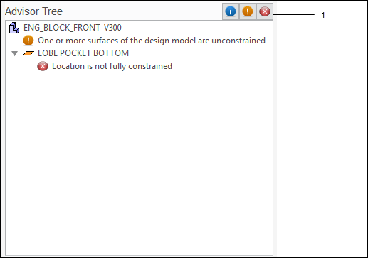
1. Advisor Tree Toolbar
The Advisor Tree shows the objects in the model that may have problems. A brief description of each potential problem is listed under the corresponding object. Each message is marked with an icon that indicates it severity:
Icon | Severity | Description |
|---|---|---|
Information | The message indicates an issue that may or may not be a problem. | |
Warning | The message indicates a minor problem with the model. | |
Error | The message indicates a significant problem that should be addressed. |
Each of the messages displayed in the Advisor Tree provides a very brief description of the problem. If you double-click on a message, a more detailed description of the problem is displayed in the browser.
The toolbar at the top of the Advisor Tree has buttons that correspond to the severity icons described above. Selecting one of these buttons toggles the display of all messages of the corresponding severity.
Tolerance Feature Dashboard
When you add or modify a feature, the Tolerance Feature dashboard provides the controls necessary to define the properties of the feature.
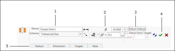
1. Feature properties
2. Geometric Control Properties
3. Datum Feature Properties
4. Action Buttons
5. Property Panels
Dashboard Property Regions
The dashboard has the following regions for defining the properties of the feature:
• Feature Properties — Define the feature properties. (See Feature Properties for more information.)
• Geometric Control Properties — Define the dimension and geometric tolerances to apply to the feature. (See Geometric Control Properties for more information.)
• Datum Feature Properties — Define properties for a datum feature. (See Datum Feature Dashboard for more information.)
Property Panels
You can access optional properties on the property panels:
• Feature Panel — Provides controls for modifying or redefining the surface references for the feature. (See Feature Slide-Out Panel for more information.) For patterns, this is replaced by the Pattern Panel which provides controls for adding or removing members of the pattern. (See Pattern Slide-Out Panel for more information.)
• Dimension Panel — Provides controls for selecting the required dimensions and reference features (See Dimension Slide-Out Panel for more information.)
• Targets Panel — Provides controls for selecting the targets for a datum established from targets (See Targets Slide-out Panel for more information.)
• Notes Panel — Define a note for the feature.
Action buttons
The following action buttons are available:
•  – Accept and Repeat — Accept the properties defined in the dashboard and then repeat the "Tolerance Feature" process.
– Accept and Repeat — Accept the properties defined in the dashboard and then repeat the "Tolerance Feature" process.•  – Accept — Accept the properties defined in the dashboard.
– Accept — Accept the properties defined in the dashboard.•  – Cancel — Cancel the operation and discard any changes.
– Cancel — Cancel the operation and discard any changes.There are some fields that are required. When required fields do not have valid values specified, the Accept and Repeat and Accept are colored orange. When all of the required values have been specified, those buttons will be displayed with their normal colors (as pictured above).
Main Workflow
The flowchart below shows the typical workflow in GD&T Advisor.
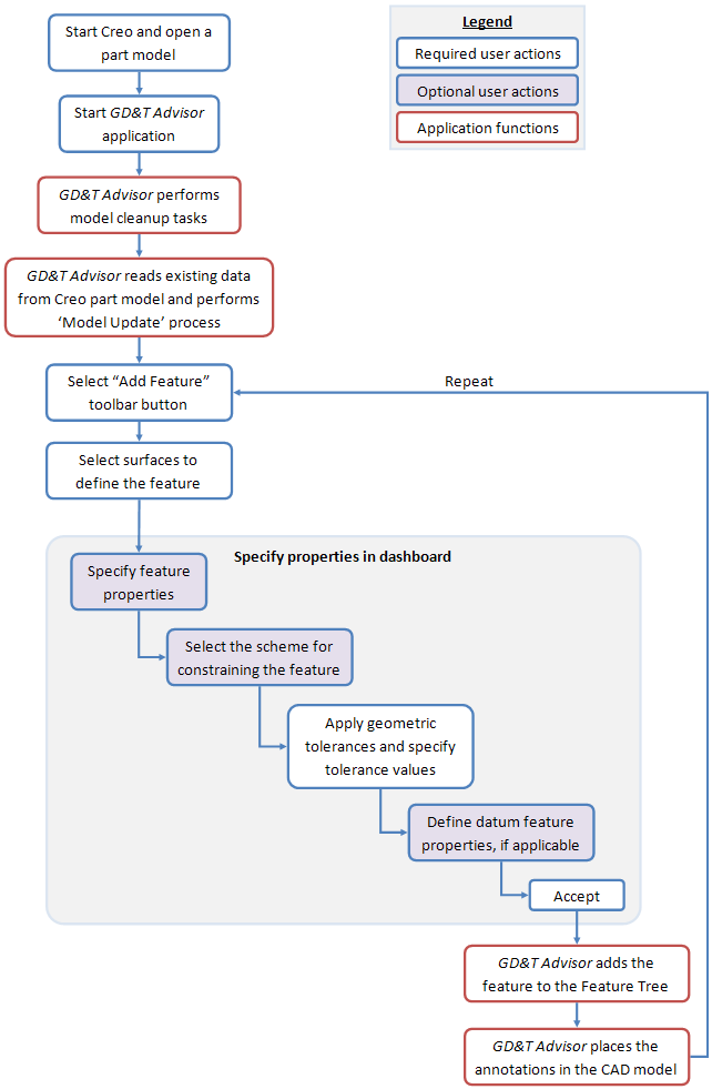
Note that some options and default values are controlled by the settings defined in the application options. It is a good idea to review the application options prior to defining a GD&T Advisor model for a part. See Application Options for more information.