Workflow to Manually Designate Components and Route Cables
Prior to routing a wire, cable, or sheath, you must define or read in the spool files for each of them. For more information, see topics Creating Spools and Modifying Spools.
The workflow for manually designating components and routing cables is as follows:
1. Manually Designate the Components
a. Click  Auto Designate > .
Auto Designate > .b. Select the component that you want to designate as connector. The DES CONN menu appears.
c. Click  in the Enter file name to read connector parameter from (DEFAULT) box to use the default connector parameters. The MOD CONN menu appears.
in the Enter file name to read connector parameter from (DEFAULT) box to use the default connector parameters. The MOD CONN menu appears.2. Select the coordinate system that you want to assign as entry ports to carry the cable and wire on the connector.
a. Click Entry Ports on the MOD CONN menu and select the coordinate system.
b. Click OK in the Select dialog box.
c. Click on the Enter internal length of cable inside the connector box. The PORT TYPE menu appears.
on the Enter internal length of cable inside the connector box. The PORT TYPE menu appears.d. Select a port type.
▪ Wire allows to route a single wire. You cannot route a cable or multiple wires to a wire entry port.
▪ Round and Flat allows multiple connections. A ribbon cable is routed to a flat entry port.
e. Click Done on the ENTRY PORT menu and Done on the MOD CONN menu.
3. Designate all components as connectors in the cabling assembly.
4. Route wires and cables through entry ports on the connectors.
Example
Refer the cabling_assembly.asm sample assembly to learn how to manually designate components and auto route cables through the entry ports of the connectors. Sample models are available at <Creo load point>\Common Files\help\sample_models\cabling. Open the cabling_assembly.asm. Select MANUAL_ROUTE from the  Saved Orientations list. Set MANUAL-ROUTING as the working harness.
Saved Orientations list. Set MANUAL-ROUTING as the working harness.1. Click Auto Designate >
Auto Designate > 2. Select the component as shown in the figure.
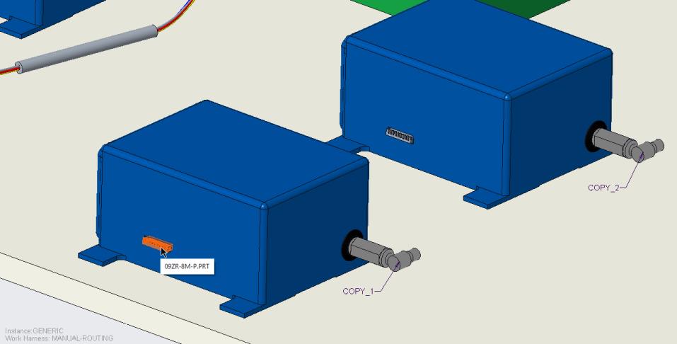
The DES CONN menu appears.
3. Click Enter Name. The Enter file name to read connector parameter from (DEFAULT) box opens.
4. Click to use the default parameters. The MOD CONN menu appears.
to use the default parameters. The MOD CONN menu appears.5. Click Entry Ports to select the coordinate system on the connector to be used as the ports. The Select dialog box opens.
6. Click Add/ Modify and press CTRL F to open the Search Tool dialog box.
7. Click Find Now. The entry ports associated with the selected component appear.
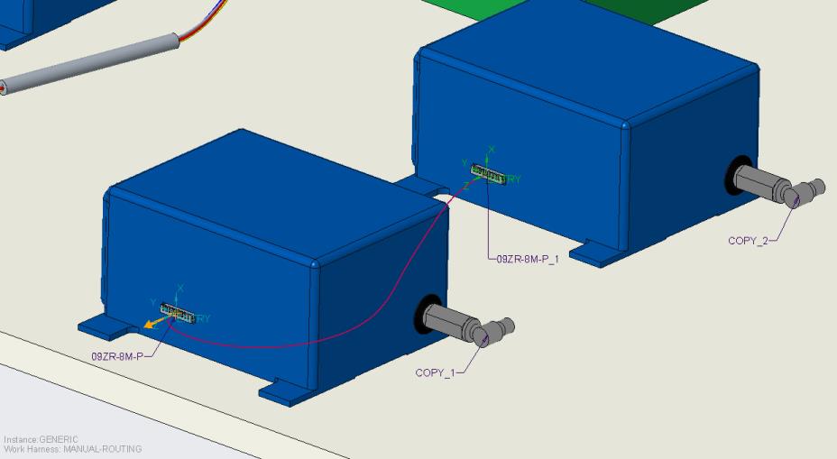
8. Select entry port ENTRY:F9(CSYS):09ZR-8M-P, click  to move it to the items selected list, and click Close. The entry port is selected and highlighted in the graphics window.
to move it to the items selected list, and click Close. The entry port is selected and highlighted in the graphics window.9. Click OK in the Select dialog box.
10. Click on the Enter internal length of cable inside the connector box. The PORT TYPE menu appears.TipThe PORT TYPE menu does not appear if the coordinate system is not designated. Use the Search Tool to ensure the coordinate system is selected and you are able to define the port type.
on the Enter internal length of cable inside the connector box. The PORT TYPE menu appears.TipThe PORT TYPE menu does not appear if the coordinate system is not designated. Use the Search Tool to ensure the coordinate system is selected and you are able to define the port type.11. Select ROUND as the port type.
12. Click Done on the ENTRY PORT menu.
13. Click Done on the MOD CONN menu.
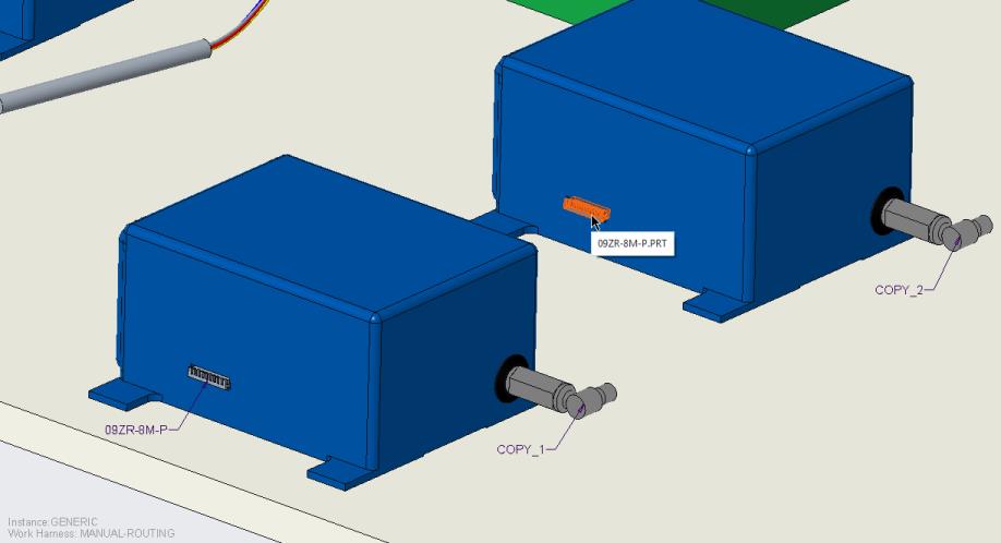
14. Follow steps 1 – 13 to designate the other component shown in the figure.
15. Click  Route Cables to open the Route Cables dialog box.
Route Cables to open the Route Cables dialog box.16. Click No in the Component Designation message box.
17. In the Route Cables dialog box, click  to route a wire.
to route a wire.Ensure that the spools have been read in before you start routing wires and cables. |
18. Select the first connector from the graphics window. The SEL ENTRYPRT menu appears.
19. Click ENTRY and Done Sel to specify the From location.
20. Select the other connector from the graphics window. The SEL ENTRYPRT menu appears.
21. Click ENTRY and Done Sel to specify the To location.
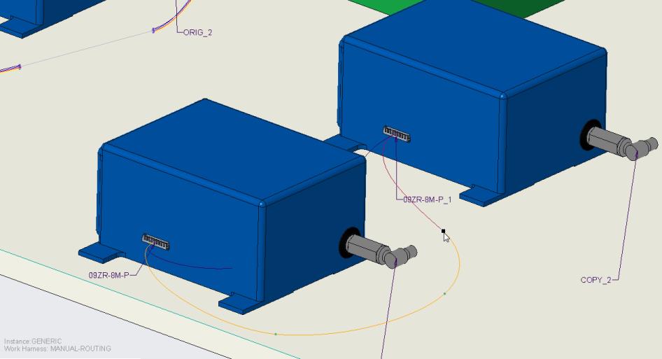
22. Click Apply. The wire is routed through the entry ports of the two connectors.
23. Click Location. The Location tab opens.
24. Click in the graphics window to add locations as shown in the figure.