Creating Spools
A spool defines various parameters for a wire, cable, or sheath. A spool of the respective type must be defined or available before a wire, cable, or sheath can be routed in a cabling design. Cabling utilizes the spool information to create and regenerate the 3D graphical representation.
The Electrical Parameters dialog box enables you to create and modify spools. Any updates made to the Spool Parameters after the wire, cable, or sheath are routed will be reflected in the 3D graphical representation model after it is regenerated.
While routing a wire, cable, or sheath using the schematic information from Creo Schematics, the spools are automatically created. Modifying the automatically created spool information causes a mismatch between the 2D logical data and 3D design. To avoid this mismatch, PTC recommends that you make changes in Creo Schematics and then re-import the information. Re-importing logical data resets the spool information according to the information defined in the schematic.
Spool Parameters
The following table lists all system spool parameters. The table also lists which parameter is required, optional, and recommended for the specific type of spool. You can also add a user defined parameter to define specific requirements.
• R=Required
• O=Optional
• RD=Recommended
|
Parameters
|
Description
|
Wire
|
Cable
|
Cable Conductor
|
Sheath
|
|---|---|---|---|---|---|
|
NAME
|
Name of the spool.
|
R
|
R
|
R
|
|
|
TYPE
|
The type of spool.
|
WIRE
|
PREFAB
|
SHEATH
|
|
|
MIN_BEND_RADIUS
|
Sets the minimum bend radius that the cable or sheath can take when it is routed.
When used with the DEFINE and ENDDEF cable spool parameters to define a conductor, the value of this parameter overrides the DEFAULT_COND_BEND_RAD parameter value.
|
R
|
R
|
O
|
O
|
|
THICKNESS
|
The diameter of the WIRE or ROUND type cable and the thickness of the FLAT type cable.
This value is utilized to offset the centerline of the cable from the surfaces when you place a location.
When used with the DEFINE and ENDDEF cable spool parameters to define a conductor, the value of this parameter overrides the DEFAULT_COND_THICKNESS parameter value.
|
R
|
R
|
O
|
|
|
UNITS
|
Sets the units for the thickness of the spool, for example, millimeter , foot, or inch.
|
R
|
R
|
R
|
R
|
|
NUM_CONDUCTORS
|
The total number of conductors present in a cable.
|
R
|
|||
|
COLOR
|
Establishes the color of the cable, wire insulation, or sheathing. The value for this parameter must map to the name of a color in the Appearances Manager.
|
RD
|
RD
|
RD
|
RD
|
|
DENSITY
|
Linear density, mass per unit length. The MASS_UNITS and UNITS parameters should also be specified for the wire, cable, or sheath.
If you do not use the MASS_UNITS and UNITS parameters, the default units for the value of the DENSITY parameter are derived from the assembly.
|
RD
|
RD
|
RD
|
RD
|
|
MASS_UNITS
|
The mass units for example, ounce, pound, or kilogram. Specify this parameter when the DENSITY parameter is used.
|
RD
|
RD
|
RD
|
RD
|
|
OUTER_DIAMETER
|
Indicates the outer diameter of the tube sheathing. The units used are specified by the UNITS parameter.
|
R
|
|||
|
PRESHRINK_INNER_DIAMETER
|
Indicates the pre-shrunk diameter of SHRINK sheathing. This value specifies the inner diameter only and allows the system to check interference between the shrink sheathing itself and the wires, cables, and bundles within it. The thickness of sheathing is specified by the parameter WALL_THICKNESS. A value of 0 (default) forces the SYSTEM to NOT check for any interference.
|
R
|
|||
|
SHEATH_TYPE
|
Specifies the type of sheathing for this spool. Valid values are TAPE, TUBE, and SHRINK
|
R
|
|||
|
WALL_THICKNESS
|
Indicates the thickness of the sheathing. The units used are specified by the UNITS parameter.
|
R
|
|||
|
Optional Parameters
|
|||||
|
DEFAULT_COND_BEND_RAD
|
Sets the default minimum bend radius for all conductors in the cable. The value of this parameter can be overridden by specifying a value for the MIN_BEND_RADIUS spool parameter in the conductor definition.
|
O
|
|||
|
DEFAULT_COND_THICKNESS
|
Sets the default thickness for all conductors in a cable. The value of this parameter can be overridden by specifying a value for the THICKNESS spool parameter in the conductor definition.
|
O
|
|||
|
COLOR_CODE
|
Establishes the code of the color
|
O
|
O
|
O
|
O
|
|
INSUL_TYPE
|
Describes the insulation type, such as, fiber, teflon, or tefzel.
|
O
|
O
|
O
|
|
|
LINEAR_RESISTANCE
|
Sets the linear resistance for the spool.
|
O
|
O
|
||
|
LINESTYLE
|
Changes the line style for cable or sheath spools. If you set this parameter for a sheath spool, the line styles assigned to a bundle overrides this parameter value. The following line styles are permitted: SOLID FONT (default), DOTFONT, CTRLFONT, PHANTOMFONT, DASHFONT, CTRLFONT_S_L, CTRLFONT_L_L, CTRLFONT_S_S
|
O
|
O
|
O
|
|
|
OUTER_SHIELD_LINEAR_RESISTANCE
|
Specifies linear resistance of the wire's outer shielding.
|
O
|
|||
|
SHIELD_TYPE
|
A text string indicating cable shield type.
|
O
|
|||
|
SHIELD_LINEAR_RESISTANCE
|
Specifies linear resistance of the wire's shielding.
|
O
|
|||
|
CABLE_JACKET_REPORT_NAME
|
Use the default value DEFAULT, in which case the name of the cable shows in the report table. Any other value is interpreted as plain text. For example, &cable_name has no special meaning.
|
O
|
|||
|
CABLE_SHIELD_REPORT_NAME
|
Use this name for the cable symbol if the cable is shielded.
|
O
|
|||
|
LIN_CAP_TO_ITEM
|
Specifies linear electric capacity between items.
|
O
|
|||
|
LIN_CAP_ITEM_TO_SHIELD
|
Specifies linear electric capacity between items and shield.
|
O
|
|||
|
LIN_CAP_ASSEM_ITEM_TO_SHIELD
|
Specifies linear electric capacity between assembly items and shield.
|
O
|
|||
|
OUTER_SHIELD_THICKNESS
|
Specifies thickness of the outer shielding of the wire.
|
O
|
|||
|
WIRE_CONSTRUCTION
|
As a text string indicates wire construction, that is, solid, stranded, and so on.
|
||||
|
WIRE_GAUGE
|
As a text string indicates wire gauge.
|
O
|
O
|
||
|
WIDTH
|
Specifies the tape width for tape sheathing.
|
Ribbon Cable Only
|
|||
To Create a Spool
This section describes the procedure to create a wire, cable, sheath, or ribbon cable spool. Sample models are available at <Creo load point>\Common Files\help\sample_models\cabling. Refer this sample file to learn how to set the spool parameters for the cabling model. Open the file cabling_assembly.asm and click  Spools > . Select spools 3M812409, 8500004, 8700406, and BL-18GXL in the Select Spools dialog box and click OK. The Electrical Parameters dialog box displays various spools and their respective parameter values.
Spools > . Select spools 3M812409, 8500004, 8700406, and BL-18GXL in the Select Spools dialog box and click OK. The Electrical Parameters dialog box displays various spools and their respective parameter values.Perform the following steps to create a wire, cable, sheath, or ribbon cable spool:
1. Click Spools. The SPOOLS menu appears.
Spools. The SPOOLS menu appears.2. Click Create. The CREATE SPOOL menu appears.
3. Click the type of spool that you want to create.
4. At the prompt, type a new name for the type of spool you specified and press ENTER. The name of the spool must be unique. The Electrical Parameters dialog box opens.
5. Under Display For, select Connections.
6. Select the parameter values that appear by default.
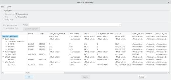
7. Specify the value for the selected parameter in the Value box, and click Apply.
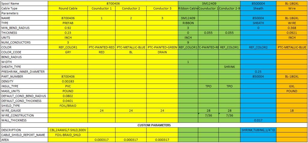
The following table displays the list of parameters and their values that are set for the sample cabling assembly (cabling_assembly.asm).
8. To add the parameters that are not available by default, click > . The Model Tree Columns dialog box opens.
a. Select the required parameter under Not Displayed. The following table lists additional parameters that you must set for each spool type.
b. Select the parameters based on the type of spool you want to create.
If you want to add user defined parameters, type the name of the parameter in the Name box. |
c. Click  to add the parameter to the Displayed list.
to add the parameter to the Displayed list.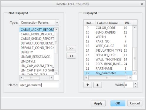
d. Click OK. The selected parameter is added to the Electrical Parameters dialog box.
9. Select the additional parameters in the Electrical Parameters dialog box.
10. Specify the value for the additional parameter in the Value box, and click Apply.
11. If you selected the NUM_CONDUCTORS parameter for cable or ribbon spool, the Conductor radio button gets enabled.
12. Under Display For, select Conductors.
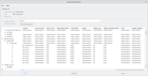
13. Expand the conductors and specify values for conductor parameters in the Electrical Parameters dialog box.
If the parameters for conductors are not displayed, add the parameters as described in Step 8. |
14. Click OK in the Electrical Parameters dialog box. A new spool is created.
The new spool can be utilized for the active assembly however, to reuse the spool in future, you must save the spool file (.spl) to your local disk. |
15. To save the spool file for future cabling assemblies:
◦ From the menu manager:
1. Click Spools. The SPOOLS menu appears.
Spools. The SPOOLS menu appears.2. Click Write. The Select Spools dialog box opens.
3. Select All Spools.
4. Click OK.
◦ From the shortcut menu:
Right-click the name of the spool from the Model Tree and click Save Spool. You can press CTRL and select multiple spools to save.
The selected spool file is saved with the extension *.spl in the working directory or to the Spool directory, if you have set the pro_spool_dir configuration option.
If you select multiple spool names, cabling creates individual spool files for each of the selected spools in the working directory. |