External Air Flow for a Truck: Exercise 4—Assigning Boundary Conditions
For boundary conditions, the fluid behavior and properties are specified at all bounding surfaces of the fluid domain.
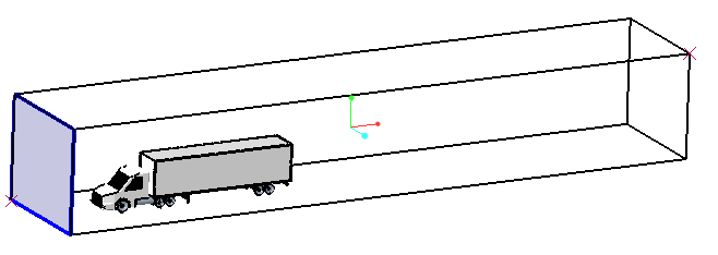
Specifying Inlet Boundary Conditions
1. Under
 Boundary Conditions
 >
 General Boundaries
, select
outside_dir1_min.
2. In the Model tab, for Flow, select the following values for the options listed:
◦ Flow — Specified Velocity
◦ Under Method, set Velocity to 20,0,0
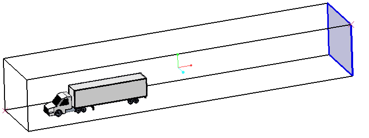
Specifying Outlet Boundary Conditions
1. Under
 Boundary Conditions
 >
 General Boundaries
, select
outside_dir1_max.
2. In the Model tab, for Flow, select the following values for the options listed:
◦ Flow — Specified Pressure Outlet
◦ Pressure — 0 Pa
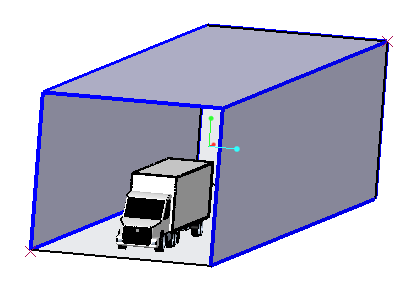
Specifying Other Boundary Conditions
1. In the Flow Analysis Tree, under
 Boundary Conditions
 >
 General Boundaries
, select
outside_dir2_max,
outside_dir3_max, and
outside_dir3_min.
2. In the Model tab, for Flow, select the following values for the options listed:
◦ Flow — Specified Pressure Outlet
◦ Under Velocity Profile, set Back Flow Velocity(optional) to 20,0,0
Specifying Expressions to calculate Drag Coefficient
1. In the Flow Analysis Tree, select
 Physics
.
2. In the
Operations group, click
 Expression Editor
.
3. In the Expression Editor box, enter the following:
V_fs = 20 # flow velocity
rho = 1.176 # density
A = 9.51474 # frontal area
#Drag force
D = flow.px@CAB + flow.tx@CAB + flow.px@TIRE_1 + flow.tx@TIRE_1 + flow.px@TIRE_2 + flow.tx@TIRE_2 + flow.px@TIRE_3 + flow.tx@TIRE_3 + flow.px@TIRE_4 + flow.tx@TIRE_4 + flow.px@TIRE_5 + flow.tx@TIRE_5 + flow.px@TIRE_6 + flow.tx@TIRE_6 + flow.px@TIRE_7 + flow.tx@TIRE_7 + flow.px@TIRE_8 + flow.tx@TIRE_8 + flow.px@TIRE_L_1 + flow.px@TIRE_L_2 + flow.tx@TIRE_L_1 + flow.tx@TIRE_L_2 + flow.px@TRAILER + flow.tx@TRAILER
plot.Drag_Force_on_Truck = D
#plot.Drag_Force_on_Truck: Drag force
#Drag coefficient
C_d = D/(0.5*rho*V_fs*V_fs*A)
plot.Coefficient_of_Drag = C_d
#plot.Coefficient_of_Drag = Coefficient of Drag
4. Click OK.


 Boundary Conditions >
  General Boundaries, select outside_dir1_min.
 Boundary Conditions >
  General Boundaries, select outside_dir1_max.
 Boundary Conditions >
  General Boundaries, select outside_dir2_max, outside_dir3_max, and outside_dir3_min.
 Physics.
 Expression Editor.