About Creating Cuts
A cut removes material from your part. The cut is made normal to the surface, as if the part were completely flat, even if it is in a bent state. The cut adopts the natural behavior, like bending and warping, when the part is bent.
You sketch cuts on a plane and projects them onto the board segment. The driving side, offset side, or both driving and offset sides of the board segment can determine the cut direction.
• Solid Cut
• Cut Normal to both Driving and Offset Surfaces
• Cut Normal to Driving Surface
• Cut Normal to Offset Surface
You can create three types of cuts:
• Board Segment Cut (solid)—Removes solid sections of material.
• Board Segment Cut (thin)—Removes only a thin section of material, like a thin cut made with a laser.
• Solid Cut—Removes solid sections of the board segment. You can extrude, revolve, sweep, blend, use quilts and make advanced solid cuts. To make a defined-angle cut, you must use the solid cut. Solid cuts can be made on an edge. See the Part Modeling Functional Area for information about solid cuts.
|  Always use the Board Segment solid cut, unless you need tapered edges. |
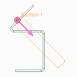
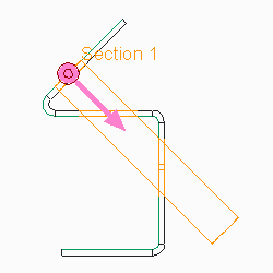
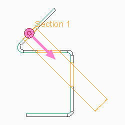
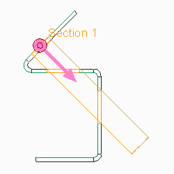
Because board segment cuts are surface cuts, you cannot make a cut to partially remove thickness. For example, you cannot cut a 1 cm deep hole in a 10 cm thick. The Blind depth command applies to cutting on bends. You can sketch the cut to the edge of the bend and project it a blind depth down the bent segment, saving you the time of unbending the segment, making the cut, and bending back the segment.
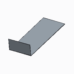
• Original Bent Segment
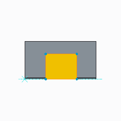
• Blind Cut Sketch
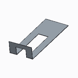
• Blind Cut
| • Cutting on angles or bend areas might require a larger dimension scale for proper clearance. • Cuts can be used to create notch and punch UDFs. |
