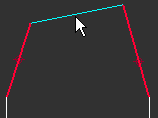
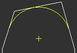
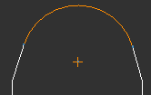
To Create a Fillet
A fillet rounds the corner of a selected intersection.
|
|
 If you select Parametric sketching in the Sketch Preferences dialog box before fillet creation, and select model edges as fillet references, then the selected model edges are automatically converted to draft entities on fillet creation. If you set your parametric sketching preferences to Erase model edges behind draft entities, the relevant model edges are erased when the fillet is complete. The Erase model edges behind draft entities option is selected by default when you select Parametric sketching in the Sketch Preferences dialog box. |
To Create a Fillet (2 Tangent Edges)
1. Click
Sketch >
 Fillet
. The
Select dialog box opens.
2. Select either a point on a model edge or a draft entity as the first fillet reference. Ensure that you select a point close to the desired start point of the fillet, because your selection point determines the default radius.
3. Press CTRL and select a model edge or draft entity as the second fillet reference. You can select multiple sets of references to sketch several fillets simultaneously.
4. By default, the system provides a radius value based on your selection point locations. You can type a new radius value or accept the default. Click OK in the Select dialog box. The Fillet Properties dialog box opens.
5. In the Radius Value box, the calculated or the most recently used fillet radius value, if available, is selected. You can also type a new value.
6. Under Trim style, select from the following trim styles to define how to display the intersection of the tangent edges:
Full trim—Deletes the intersection, displaying only the fillet intersection. | |
Thin line trim—Displays the intersection with thin lines, with the fillet in normal pen width. | |
Solid line trim—Displays both the intersection and fillet in the normal pen width, and any overlapping of intersecting fillet references is trimmed. | |
Half trim—Displays half the intersection, while deleting one of the tangent lines. The fillet is displayed in normal pen width.  is available for selection when Half trim is selected. | |
No trim—Displays the entire intersection and fillet in normal pen width; any overlapping remains. | |
|  The Complete loop check box is available for selection if you have selected multiple fillet references and the first and last references intersect, either theoretically or physically. If available for selection, the Complete loop check box is selected by default. When selected, a fillet is automatically added to complete the loop between the first and last selected references. |
7. Click OK in the Fillet Properties dialog box to complete the fillet creation. The fillet appears in the drawing.
8. Click OK in the Select dialog box or middle-click to quit fillet creation.
To Create a Fillet (3 Tangent Edges)
You can select multiple sets of fillet references to sketch multiple fillets simultaneously. You must select the references for 3 tangent fillets in the specified order: start point, end point, midpoint.
1. Click
Sketch and then click the arrow next to
 Fillet
.
2. Click
 3 Tangent Fillet
. The
Select dialog box opens.
3. Select a point on a model edge or draft entity as the first fillet reference. The first fillet reference is the start point for the fillet.
4. Select a model edge or draft entity as the second fillet reference. The second fillet reference is the end point for the fillet. The start and end points of the fillet are highlighted.
5. Select a model edge or draft entity as the final fillet reference. The third fillet reference is the midpoint of the fillet.
|  If the references are valid, the fillet appears in the drawing and remains selected. |
6. Click OK in the Select dialog box or middle-click to confirm the fillet creation. The fillet is created tangent to the three edges.
Fillet References | Nonparametric Sketching | Parametric Sketching |
| | |
|  You cannot modify fillets that reference three tangent edges. If you want to make changes to a fillet, you must delete the existing fillet and create a new fillet. |
 Fillet. The Select dialog box opens.


 is available for selection when Half trim is selected.

 Fillet.
 3 Tangent Fillet. The Select dialog box opens.

