Exercise: Performing Optimization for Maximum Stiffness in the Structure Study
In this exercise, you learn how to optimize deformation of a solid.
Downloading Model for the Exercise
Click here to access the downloads page. Click English to download the gd_exercise_structure.zip folder to your computer and then extract it. The extracted folder contains the file that you will use in this tutorial exercise.
Workflow
1. Open the model.
2. Define design spaces.
3. Add constraints and loads.
4. Define design criteria for the study.
5. Define optimization settings.
6. Perform optimization.
7. View simulation results.
8. Create a Generative Design Feature (GDF).
9. Perform deviation analysis.
Open the Model
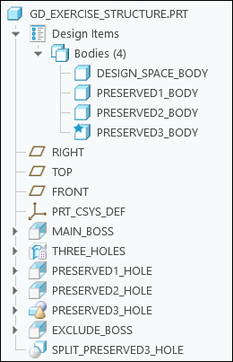
1. Set gd_exercise_structure as the Working Directory, and then open gd_exercise_structure.prt.
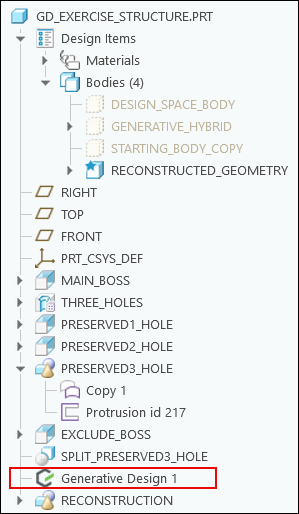
The following graphic shows the Model Tree:
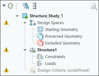
2. Click > .
The following graphic shows the Generative Tree:
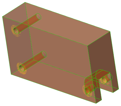
Define Design spaces
1. Designate a body as the starting geometry as follows:
a. Select DESIGN_SPACE_BODY from the graphics window or the Model Tree.
b. Click  Starting Geometry. The selected body becomes partially transparent.
Starting Geometry. The selected body becomes partially transparent.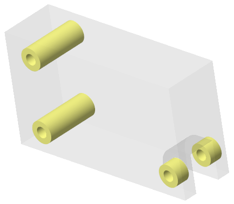
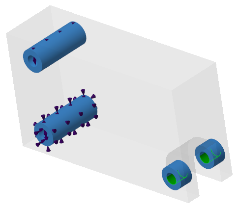
2. Designate bodies as preserved geometry as follows:
a. Press Ctrl and select PRESERVED1_BODY, PRESERVED2_BODY, and PRESERVED3_BODY from the graphics window or the Model Tree.
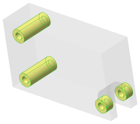
b. Click  Preserved Bodies. The selected bodies become blue.
Preserved Bodies. The selected bodies become blue.
Add Constrains and Loads
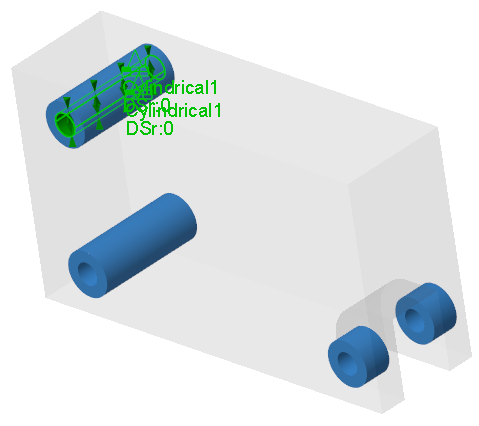
1. Add a cylindrical constraint as follows:
a. Select the inner surface of PRESERVED1_HOLE.

b. Click >  Cylindrical. The Cylindrical Constraint dialog box opens.
Cylindrical. The Cylindrical Constraint dialog box opens.c. Click OK.
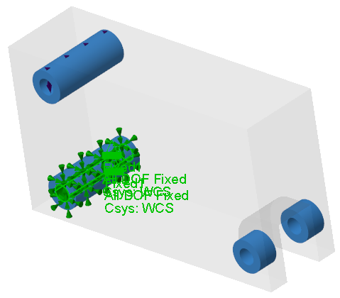
2. Add a fixed constraint as follows:
a. Select the inner surface of PRESERVED2_HOLE.
b. Click >  Fixed. The Fixed Constraint dialog box opens.
Fixed. The Fixed Constraint dialog box opens.c. Click OK.
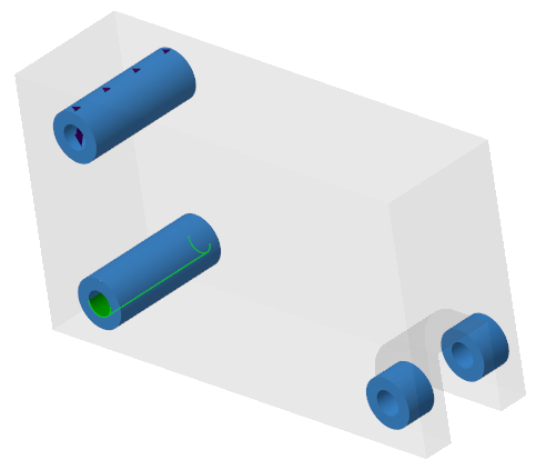
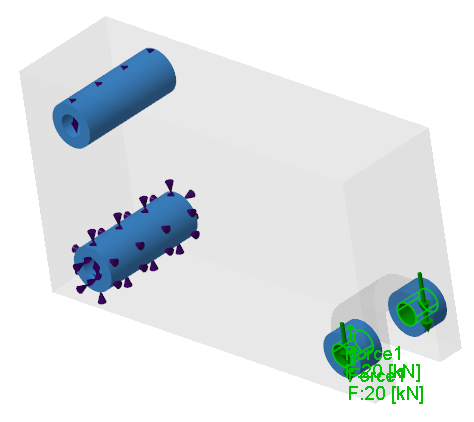
3. Add a force load as follows:
a. Select the inner surface of PRESERVED3_HOLE.
b. Click >  Force. The Force Load dialog box opens.
Force. The Force Load dialog box opens.c. In the Y box, type -1.
d. In the Magnitude box, type 20.
e. In the Units box, select kN.
f. Click OK.
Define Design Criteria for the Study
1. Click  Add Design Criteria. The Design Criteria dialog box opens.
Add Design Criteria. The Design Criteria dialog box opens.2. Define the design goal as follows:
a. In the Design Goals box, select Maximize stiffness, if not selected already.
b. In the Limit volume box, type 15 and in the adjacent box, select %.
3. Add the material as follows:
a. Click Add Material. The Materials dialog box opens.
The master material of the part appears in the Materials in Model list. |
b. Under Material Directory, double-click the Standard-Materials_Granta-Design directory.
c. Double-click the Ferrous_metals directory.
d. Double-click Steel_cast to select it. The selected material is added to the Materials in Model list.
e. Click Select.
STEEL_CAST is set as the active material. |
4. Click OK.
Define Optimization Settings
1. Click  Study Settings. The Study Settings dialog box opens.
Study Settings. The Study Settings dialog box opens.2. In the Fidelity box, select 3.
3. In the Min. element size box, type 6.00.
4. In the Max. iterations box, type 256.
5. Click OK.
Perform Optimization
• Click  Optimize to start optimization.
Optimize to start optimization.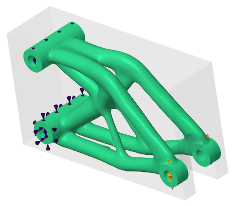
View Simulation Results
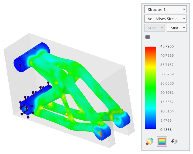
1. Click  Display Simulation Results. A legend widget appears along with the FEA fringe plot.
Display Simulation Results. A legend widget appears along with the FEA fringe plot.2. View the simulation results for different result types as follows:
a. In the legend widget, select Von Mises Stress.
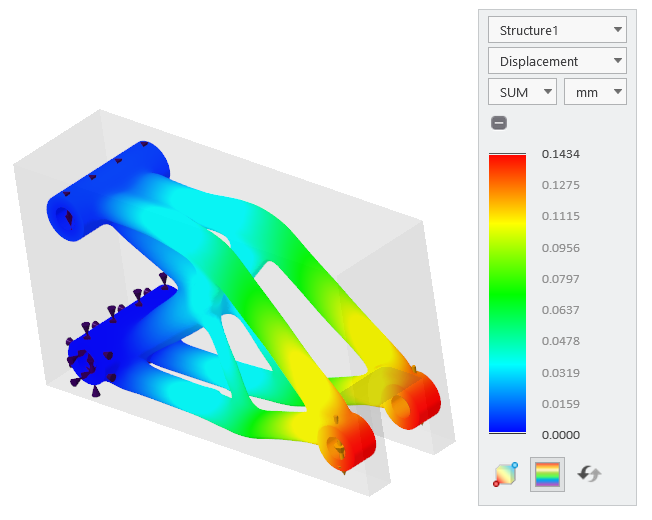
b. In the legend widget, select Displacement.
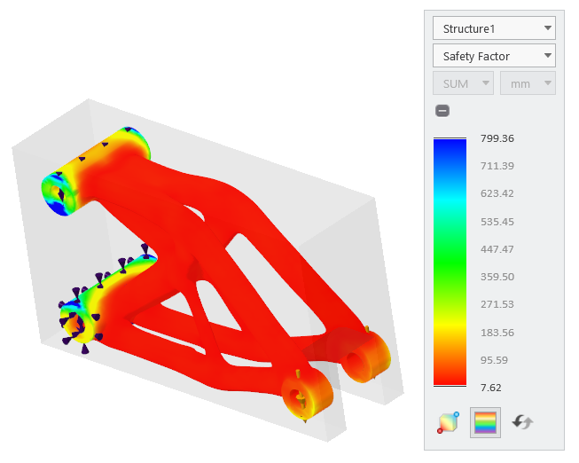
c. In the legend widget, select Safety Factor.
3. Animate the deformation as follows:
a. Click  Animate Deformation. The Animation Deformation Settings dialog box opens.
Animate Deformation. The Animation Deformation Settings dialog box opens.b. Move the Speed and Scale sliders to change the animation speed and scale.
c. Click  to play and click
  to stop the animation.
to play and click to stop the animation.Animate the deformation for different result types. |
d. Click Close.
Create a Generative Design Feature (GDF)
1. Click  Generate Design. The Generate Result dialog box opens.
Generate Design. The Generate Result dialog box opens.2. In the Result output box, select Current Part.
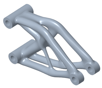
3. Under Geometry Output, click Reconstructed.
4. Select  as the Resolution level.
as the Resolution level.5. Click Generate. The Generative Design 1 feature appears in the Model Tree.
The Generative Design application closes. |
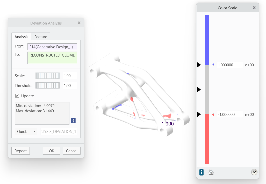
Perform Deviation Analysis
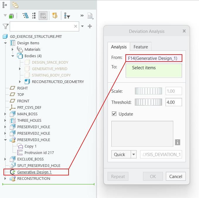
1. Click > >  Deviation. The Deviation Analysis dialog box opens.
Deviation. The Deviation Analysis dialog box opens.2. Click in the From box and select Generative Design 1 in the Model Tree.
3. Click in the To box and select RECONSTRUCTED_GEOMETRY in the Model Tree.
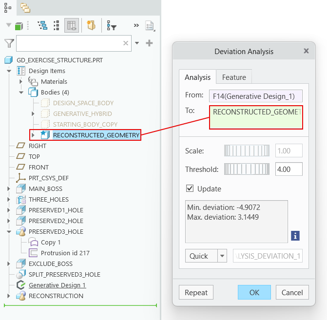
4. In the Threshold box, type 1. The deviation between the optimization result and the reconstructed geometry is displayed in the graphics window.