Contact Between Bodies
Use contact to connect bodies in a model. Define a contact between an undesignated body and the starting geometry or between two undesignated bodies. The bodies are connected with bonded interface and always remain touching each other during analysis. The applied loads and constraints transfer between the connected bodies. All contacts defined in a study are considered when generating the final design.
When working within an assembly context, you can define contacts between bodies from different parts in the assembly.
When creating bonded contacts, you can select the surfaces where you want the starting geometry to connect to the undesignated body. This is called the interaction region. An offset is created only around the interaction region. For more information, see Example: Creating a Contact with an Interaction Region.
To Create a Contact
1. Click  Contact. The Contact Definition dialog box opens.
Contact. The Contact Definition dialog box opens.2. [Optional] Specify a name for the contact in the Name box.
3. Select the first body from the Model Tree or the graphics window. The body appears in the body collector in the dialog box.
4. Repeat step 3 to select the second body.
5. Optionally, specify a positive offset value that is greater than three times the element size.
You can specify the offset only when the starting geometry is selected as a reference. However, you cannot specify the offset when a starting shape is selected as a reference. Specifying an offset creates preserved geometry around the undesignated body inside the starting geometry. |
6. Optionally, select the surfaces where you want the starting geometry to connect to the undesignated body as the interaction region.
7. Click OK. A rolling ball offset is created around the undesignated body or the interaction region, inside the starting geometry.
The selected bodies are connected with a bonded interface and a Contacts node is created in the Generative Tree. Expand > nodes to view all interfaces defined for the model.
A  Connected Geometry node is also created in the Generative Tree, with the selected bodies added under it as deformable bodies.
Connected Geometry node is also created in the Generative Tree, with the selected bodies added under it as deformable bodies.Deformable Bodies
Deformable bodies  undergo deformation during optimization based on the applied loads.
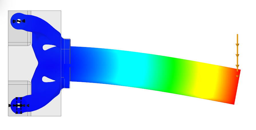
undergo deformation during optimization based on the applied loads.The following graphic shows the displacement of a deformable body:
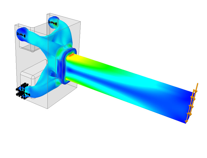
The following graphic shows the stress distribution in a deformable body:
Rigid Bodies
Rigid bodies  are stiff, and they do not undergo any deformation during optimization.
are stiff, and they do not undergo any deformation during optimization.The material of the rigid body must have isotropic symmetry, and its density must be defined. You can also select an isotropic material from the materials library. During optimization, only the density is considered. Remote load and mass with deformable behavior are not supported on rigid bodies. Bodies cannot be marked as rigid bodies in a thermal study. |
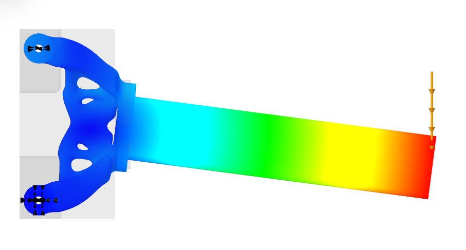
The following graphic shows the displacement of a rigid body:
The following graphic shows the stress distribution in a rigid body:
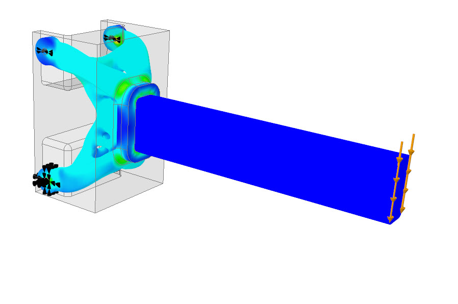
The stress value is 0 MPa for a rigid body. |
To Convert a Body to a Rigid Body
1. In the Generative Tree, expand the Connected Geometry node.
2. Select the deformable body, right-click, and then click Convert to Rigid. The selected body becomes a rigid body.
To Convert a Body to a Deformable Body
1. In the Generative Tree, expand the Connected Geometry node.
2. Select the rigid body, right-click, and then click Convert to Deformable. The selected body becomes a deformable body.
To Modify a Contact
In the Generative Tree, select the contact that you want to modify, and on the mini toolbar click  Edit Definition. The Contact Definition dialog box opens. You can change the connected bodies.
Edit Definition. The Contact Definition dialog box opens. You can change the connected bodies.To Delete a Contact
Right-click a contact from the Generative Tree, and click  Delete.
Delete.To Rename a Contact
Right-click a contact in the Generative Tree, and click Rename.