Inserting Custom Components, Splices, and In-Line Connectors
To Insert a Custom Component
Refer the cabling_assembly.asm sample assembly to learn how to insert a custom component in the cabling model. Sample models are available here To insert a custom component, complete the following steps:
1. Select  Insert Custom Component from the Insert Components drop down list.
Insert Custom Component from the Insert Components drop down list.2. In the Custom Components tab, click  . The Open dialog box opens. Select the component that you want to insert along a cable and click Open. You can select a part that has only a surface or datum curve or at least a datum coordinate system to define the entry ports. The part appears in the component window, and it appears in a separate window in the Model Tree.
. The Open dialog box opens. Select the component that you want to insert along a cable and click Open. You can select a part that has only a surface or datum curve or at least a datum coordinate system to define the entry ports. The part appears in the component window, and it appears in a separate window in the Model Tree.3. From the model displayed in the component window, select a coordinate system. The selected coordinate system appears in the Comp. Attachment box of the Placement group.
4. From the graphics window select an existing location where you want to place the part. The selected location appears in the Cable location box.
5. Select the placement constraints type:
◦ Tangent to cable— Attaches the attachment coordinate system to the location selected earlier with its z-axis tangent to the cable segment at the location.
◦ Aligned to reference— Attaches the splice selected to the selected plane, edge, coordinate system, coordinate system axis, or datum axis. The z-axis of the coordinate system is normal to the selected plane or aligned to the selected curve, edge, axis, or coordinate system. You can modify the direction of the attachment location to be parallel to the z-axis of the attachment entry port.
Use  to switch the orientation between the positive and negative z-axis of the coordinate system.
to switch the orientation between the positive and negative z-axis of the coordinate system.6. Specify the required orientation in the Rotate About z-axis group:
◦  — Specify rotation in degrees about the z-axis of component's attachment reference.
— Specify rotation in degrees about the z-axis of component's attachment reference.◦  —Align the x-axis of the component's attachment reference to the selected reference.
—Align the x-axis of the component's attachment reference to the selected reference.◦  —Align the y-axis of the component's attachment reference to the selected reference.
—Align the y-axis of the component's attachment reference to the selected reference.7. The Cable Paths table provides a structured view of cable routing through components. You can also set and modify the visibility of cable paths inside a custom component to:
◦ Yes— The internal segment for a cable is displayed between the entry and exit location in the 3D view.
◦ No— The wire display terminates at one entry port and resumes at another entry port. This option is selected by default.
To streamline editing, use the Propagate to All command from the right-click menu on a collector to apply the selected reference across all rows in the same column.
8. Click  OK. The custom component is inserted into the cable path.
OK. The custom component is inserted into the cable path.To Insert a Splice
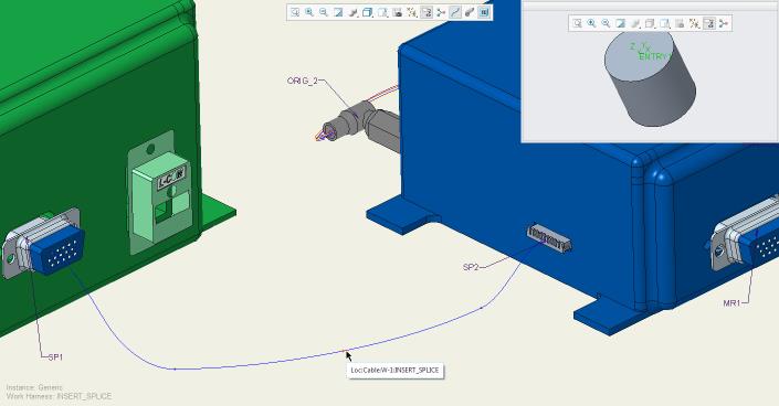
Refer the cabling_assembly.asm sample assembly to learn how to insert a splice in the cabling model. Sample models are available here. Open cabling_assembly.asm. Set INSERT_SPLICE as the working harness. Then select INSERT_SPLICE from the  Saved Orientations list.
Saved Orientations list.To insert a splice, complete the following steps:
1. Select  Insert Splice from the Insert Components drop down list.
Insert Splice from the Insert Components drop down list.2. In the Splice tab, click .The Open dialog box opens. Select the splice that you want to insert along a cable and click Open. You can select a part that has only a surface or datum curve or at least a datum coordinate system to define the entry ports. The splice part appears in the component window, and it appears in a separate window in the Model Tree.
.The Open dialog box opens. Select the splice that you want to insert along a cable and click Open. You can select a part that has only a surface or datum curve or at least a datum coordinate system to define the entry ports. The splice part appears in the component window, and it appears in a separate window in the Model Tree.In the sample assembly, select Splice.prt and click Open.
3. From the model displayed in the component window, select a coordinate system. The selected coordinate system appears in the Comp. Attachment box of the Placement group.
In the sample assembly, select ENTRY_1 from the splice component window.
4. From the graphics window select an existing location where you want to place the splice. The selected location appears in the Cable location box.
5. Select the Placement Constraints type.
◦ Tangent to cable— Attaches the attachment coordinate system to the location selected earlier with its z-axis tangent to the cable segment at the location.
◦ Aligned to reference— Attaches the splice selected to the selected plane, edge, coordinate system, coordinate system axis, or datum axis. The z-axis of the coordinate system is normal to the selected plane or aligned to the selected curve, edge, axis, or coordinate system. You can modify the direction of the attachment location to be parallel to the z-axis of the attachment entry port.
Use to change the orientation from the positive-z to the negative-z of the coordinate system, or vice-versa.
to change the orientation from the positive-z to the negative-z of the coordinate system, or vice-versa.In the sample assembly, select the location as shown in the figure.
Reference designators can be set only after the splice has been created in the Cabling Data tool, for more information refer to the About Cabling Data tool topic. |
6. Specify the required orientation in the Rotate About z-axis group:
◦ — Specify rotation in degrees about the z-axis of component's attachment reference.
— Specify rotation in degrees about the z-axis of component's attachment reference.◦ —Align the x-axis of the component's attachment reference to the selected reference.
—Align the x-axis of the component's attachment reference to the selected reference.◦ —Align the y-axis of the component's attachment reference to the selected reference.
—Align the y-axis of the component's attachment reference to the selected reference.7. The Cable Paths table provides a structured view of cable routing through components. In the sample assembly, select W-1, click Exit Port and select the exit port ENTRY_2 from the graphics window. Set the visibility of internal cable paths within a splice to one of the following options:
◦ Yes— The internal segment for a cable is displayed between the entry and exit location in the 3D view.
◦ No— The wire display terminates at one entry port and resumes at another entry port. This option is selected by default.
To streamline editing, use the Propagate to All command from the right-click menu on a collector to apply a selected reference across all rows in the same column.
8. The Entry Ports table lists parameters such as entry port name, designation status, type, and internal length associated with the splice. On the Splice tab, select the logical name for the splice from the Designation list. The logical names are defined in the Cabling Data Object. The Entry Ports table populates default values from the logical data. Edit entry port parameters if required. The changes are saved instantly to the Cabling Data Object.
9. Click OK. The splice is inserted into the cable path.
OK. The splice is inserted into the cable path.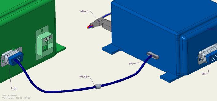
• The minimum bend radius is ignored for internal segments. Cabling assumes that the selected path is the shortest path that maintains tangency between the entry and exit z-axis unless the internal path has and shows manually added locations. • Harness Manufacturing flattens internal portions of splices and components, even when they form loops. It does not flatten complete loops. Harness Manufacturing can also flatten a virtual loop. • Ensure that either entire cables or individual conductors enter and exit the component consistently. Bundles must stop at the last location that is common to all cables. A new bundle that is manually created cannot continue after the component unless all cables in the bundle enter and leave together. • If the item goes into a component and does not stop at an entry port, it must come out as itself, and not as part of a cable or bundle. Ensure that any item entering a component also exits it without interruption. |
To Insert an In-Line Connector
To insert an in-line connector, complete the following steps:
1. Select  Insert In-Line Connector from the Insert Components drop down list.
Insert In-Line Connector from the Insert Components drop down list.2. In the In-Line Connector tab, click . The Open dialog box opens. Select the component that you want to insert along a cable and click Open. You can select a part that has only a surface or datum curve or at least a datum coordinate system to define the entry ports. The part appears in the component window, and it appears in a separate window in the Model Tree.
. The Open dialog box opens. Select the component that you want to insert along a cable and click Open. You can select a part that has only a surface or datum curve or at least a datum coordinate system to define the entry ports. The part appears in the component window, and it appears in a separate window in the Model Tree.3. From the model displayed in the component window, select a coordinate system. The selected coordinate system appears in the Comp. Attachment box of the Placement group.
4. From the graphics window select an existing location where you want to place the part. The selected location appears in the Cable location box.
5. Select the Placement Constraints type:
◦ Tangent to cable— Attaches the attachment coordinate system to the location selected earlier with its z-axis tangent to the cable segment at the location.
◦ Aligned to reference— Attaches the splice selected to the selected plane, edge, coordinate system, coordinate system axis, or datum axis. The z-axis of the coordinate system is normal to the selected plane or aligned to the selected curve, edge, axis, or coordinate system. You can modify the direction of the attachment location to be parallel to the z-axis of the attachment entry port.
Use to change the orientation from the positive-z to the negative-z of the coordinate system, or vice-versa.
to change the orientation from the positive-z to the negative-z of the coordinate system, or vice-versa.6. Specify the required orientation in the Rotate About z-axis group:
◦ — Specify rotation in degrees about the z-axis of component's attachment reference.
— Specify rotation in degrees about the z-axis of component's attachment reference.◦ —Align the x-axis of the component's attachment reference to the selected reference.
—Align the x-axis of the component's attachment reference to the selected reference.◦ —Align the y-axis of the component's attachment reference to the selected reference.
—Align the y-axis of the component's attachment reference to the selected reference.7. The Cable Paths table provides a structured view of a cable routing through components. You can also set and modify the visibility of cable paths inside an in-line connector to:
◦ Yes—The internal segment for a cable is displayed between the entry and exit location in the 3D view.
◦ No—The wire display terminates at one entry port and resumes at another entry port. This option is selected by default.
When using in-line connectors, you can also define Input Cable and Output Cable names to represent the cable segments entering and exiting the component. Edit the Input Cable and Output Cable fields to clarify cable continuity across connector points.
To streamline editing, use the Propagate to All command from the right-click menu on a collector to apply the selected reference across all rows in the same column.
8. The Entry Ports table lists parameters such as entry port name, designation status, type, and internal length associated with the connector. On the In-Line Connector tab, select the logical name for the connector from the Designation list. The logical names are defined in the Cabling Data Object. The Entry Ports table populates default values from the logical data. Edit entry port parameters if required. These changes are saved instantly to the Cabling Data Object.
9. Click OK. The in-line connector is inserted into the cable path.
OK. The in-line connector is inserted into the cable path.Cable lengths are calculated from the originating terminals to the in-line connector's coordinate system of the entry port. To add internal lengths, use the component entry port parameter, int_length, on the in-line connector. |