Exercise—Create Plies from Zones
In this exercise, you will learn how to create laminate objects using the Plies From Zones action.
Click here to access the downloads page. Click English to download the plies_from_zones_exercise.zip folder to your computer and then extract it. The extracted folder contains the model and the stack files that you will use in this exercise.
Workflow
1. Open the model.
2. Verify the settings for the exercise.
3. Define laminate zones.
4. Define zone stacks.
5. Create laminate objects based on the Do not merge option.
6. Create a laminate section.
7. Create laminate objects based on the Match stack row option.
8. Create laminate objects based on the Ignore stack row option.
Open the Model
1. Start a new Creo session.
2. Set the extracted folder as your working directory.
3. Open plies_from_zones_exercise_start.prt.
4. On the graphics toolbar, click Datum Display Filters, and then clear all the check boxes to hide all the datum display filters.
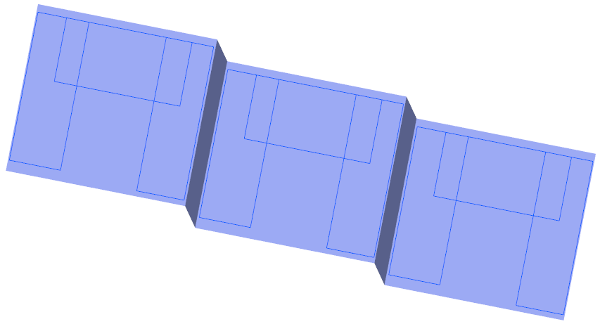
5. On the graphics toolbar, click Saved Orientations and select ORIENTATION_1. The model appears as shown in the following graphic:
Verify the Settings for the Exercise
1. In the Model Tree, select Composite 1, and then click  Edit Definition. The Composite tab opens.
Edit Definition. The Composite tab opens.2. On the Laminate Tree, click  Laminate Manager.
Laminate Manager.3. Add the Zones column (if not already present), as follows:
a. Click  Tree Columns. The Laminate Tree Columns dialog box opens.
Tree Columns. The Laminate Tree Columns dialog box opens.b. Click Reset.
c. Select Zones from the Not Displayed list and then click  .
.
d. Click OK.
4. On the Laminate Tree, click  Laminate List.
Laminate List.5. To learn how to define a laminate zone, see Define laminate zones.
Define Laminate Zones
For your convenience, some laminate zones are already created. You can create the last laminate zone as follows:
1. Click  Laminate Zone. The Laminate Zone tab opens.
Laminate Zone. The Laminate Zone tab opens.2. Select the highlighted closed loop.
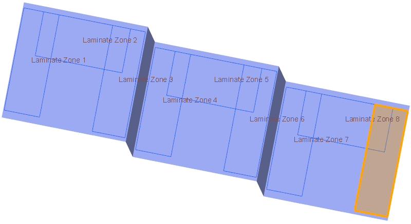
3. Click  OK. The Laminate Zone 9 is created.
OK. The Laminate Zone 9 is created.4. To learn how to create a zone stack, see Define zone stacks.
Define Zone Stacks
1. Click  Zone Stacks. The Zone Stacks dialog box opens.
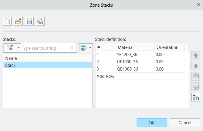
Zone Stacks. The Zone Stacks dialog box opens.2. Define Stack 1 as follows:
a. Define the first row as follows:
a. Click the cell that contains the material QE1000_36.
b. Expand the list and select YE1200_36.
c. Click Add Row.
b. Define the second row as follows:
a. In the second row, click the cell that contains the material QE1000_36.
b. Expand the list and select UE1000_36.
c. Click Add Row. Stack 1 is defined as shown in the following graphic:
3. Open Stack 2 and Stack 3 as follows:
a. In the Zone Stacks dialog box, click  . The Open dialog box opens.
. The Open dialog box opens.b. Browse to the extracted folder, select Stack 2, and then click Open.
c. Click . The Open dialog box opens.
. The Open dialog box opens.d. Browse to the extracted folder, select Stack 3, and then click Open.
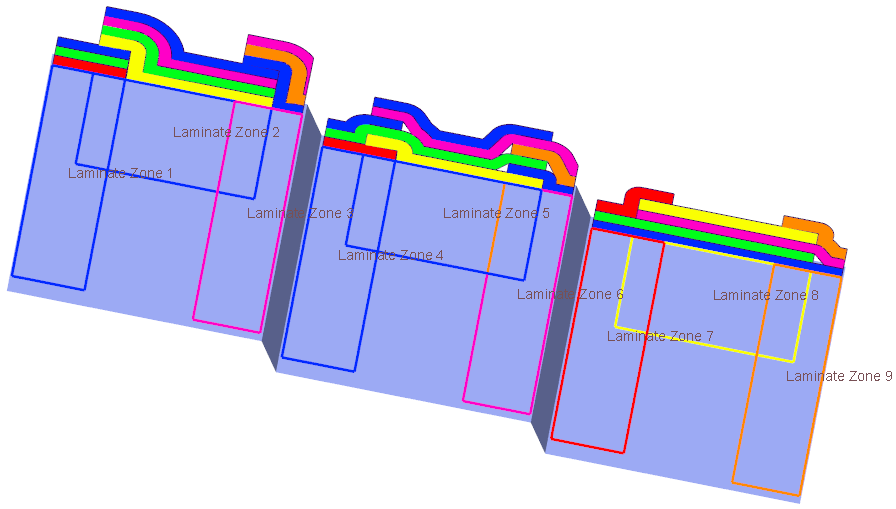
The material-orientation combinations are defined in each stack as shown in the following graphic:
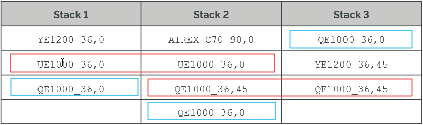
• The second row of Stack 1 and Stack 2 contains the same material-orientation combination. • The third row of Stack 2 and Stack 3 contains the same material-orientation combination. • The material-orientation combination QE1000_36,0 is defined at different rows in the three stacks. |
4. Click OK.
5. To create separate laminate objects based on the Do not merge option, see Create laminate objects based on the Do not merge option.
Create Laminate Objects Based on the Do Not Merge Option
1. Click  Plies From Zones. The Plies from Zones dialog box opens.
Plies From Zones. The Plies from Zones dialog box opens.2. Define Set 1 as follows:
a. In the Zone box, select Laminate Zone 1 from the Composite Tree or from the graphics window.
b. In the Stack list, make sure that Stack 1 is selected.
c. Click Add set.
3. Define Set 2 as follows:
a. In the Zone box, select Laminate Zone 2 from the Composite Tree or from the graphics window.
b. In the Stack list, select Stack 2.
c. Click Add set.
4. Define Set 3 as follows:
a. In the Zone box, select Laminate Zone 3 from the Composite Tree or from the graphics window.
b. In the Stack list, select Stack 3.
5. In the Merge between zones list, make sure that Do not merge is selected.
6. Click OK and then click in the empty space in the graphics window.
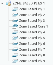
7. In the Laminate Tree, expand the ZONE_BASED_PLIES_1 group to see the created laminate objects as shown in the following graphic:

8. In the Composite Tree, expand the ZONE_BASED_PLIES_1 group to see the features of the laminate objects as shown in the following graphic:
9. On the Laminate Tree, click Laminate Manager. The Laminate Tree opens in the Laminate Manager mode as shown in the following graphic:
Laminate Manager. The Laminate Tree opens in the Laminate Manager mode as shown in the following graphic: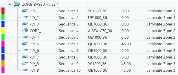
• The laminate objects are created in the order of sets specified in the Plies from Zones dialog box. • When the Do not merge option is selected, similar laminate objects are not merged between adjacent or intersecting zones. |
10. On the Laminate Tree, click Laminate List.
Laminate List.11. To see a section of the laminate, see Create a laminate section.
Create a Laminate Section
1. On the graphics toolbar, click Saved Orientations, and then select ORIENTATION_1.
2. Click  Laminate Section. The Section tab opens.
Laminate Section. The Section tab opens.3. Select the FRONT datum plane in the Model Tree to specify the Section reference.
4. In the box under Placement, type 22, and then press Enter.
5. In the Scale box, type 15, and then press Enter.
6. Click OK. A laminate section is created.
OK. A laminate section is created.A laminate section feature LAMINATEXSEC0001 is added to the Composite Tree.
If you do not see LAMINATEXSEC0001, scroll down the Composite Tree. |
7. In the Composite Tree, select LAMINATEXSEC0001, and then click  Deactivate on the mini toolbar.
Deactivate on the mini toolbar.8. Click in the empty space in the graphics window.
The laminate section shows that the similar laminate objects defined with the same material-orientation combination are not merged between the intersecting zones.
9. To create laminate objects based on the Match stack row option, see Create laminate objects based on the Match stack row option.
Create Laminate Objects Based on the Match Stack Row Option
1. Click Plies From Zones. The Plies from Zones dialog box opens.
Plies From Zones. The Plies from Zones dialog box opens.2. Define Set 1 as follows:
a. In the Zone box, select Laminate Zone 4 from the Composite Tree or from the graphics window.
b. In the Stack list, make sure that Stack 1 is selected.
c. Click Add set.
3. Define Set 2 as follows:
a. In the Zone box, select Laminate Zone 5 from the Composite Tree or from the graphics window.
b. In the Stack list, select Stack 2.
c. Click Add set.
4. Define Set 3 as follows:
a. In the Zone box, select Laminate Zone 6 from the Composite Tree or from the graphics window.
b. In the Stack list, select Stack 3.
5. In the Merge between zones list, select Match stack row.
6. Click OK and then click in the empty space in the graphics window.
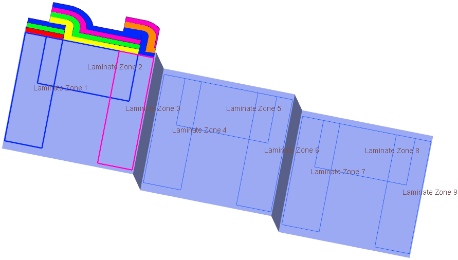
When the same material-orientation combination is defined at the same stack-row in different stacks, a merged laminate object is created on the intersecting zones. Some merged laminate objects are shown in the following graphic:
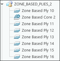
7. In the Laminate Tree, expand the ZONE_BASED_PLIES_2 group to see the created laminate objects as shown in the following graphic:

8. In the Composite Tree, expand the ZONE_BASED_PLIES_2 group to see the features of the laminate objects as shown in the following graphic:
9. On the Laminate Tree, click Laminate Manager. The Laminate Tree opens in the Laminate Manager mode.
Laminate Manager. The Laminate Tree opens in the Laminate Manager mode.10. Increase the width of the Zones column to see the names of the zones. You can also move the mouse pointer over a cell in the zones column to see the names of the zones in the tooltip.
The merged laminate objects and their zones are displayed as follows:
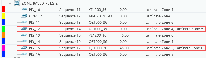
The laminate objects are created in the order of sets specified in the Plies from Zones dialog box. When the Match stack row option is selected, similar laminate objects merge between adjacent or intersecting zones when they are defined at the same row in their stacks. • Since UE1000_36,0 is defined at the same second row in Stack 1 and Stack 2, a merged ply is created on Laminate Zone 4 and Laminate Zone 5. • Since QE1000_36,45 is defined at the same third row in Stack 2 and Stack 3, a merged ply is created on Laminate Zone 5 and Laminate Zone 6. |
11. On the Laminate Tree, click Laminate List.
Laminate List.12. To create laminate objects based on the Ignore stack row option, see Create laminate objects based on the Ignore stack row option.
Create Laminate Objects Based on the Ignore Stack Row Option
1. Click Plies From Zones. The Plies from Zones dialog box opens.
Plies From Zones. The Plies from Zones dialog box opens.2. Define Set 1 as follows:
a. In the Zone box, select Laminate Zone 7 from the Composite Tree or from the graphics window.
b. In the Stack list, make sure that Stack 1 is selected.
c. Click Add set.
3. Define Set 2 as follows:
a. In the Zone box, select Laminate Zone 8 from the Composite Tree or from the graphics window.
b. In the Stack list, select Stack 2.
c. Click Add set.
4. Define Set 3 as follows:
a. In the Zone box, select Laminate Zone 9 from the Composite Tree or from the graphics window.
b. In the Stack list, select Stack 3.
5. In the Merge between zones list, select Ignore stack row.
6. In the Arrange resulting plies list, make sure that Largest at the bottom is selected.
7. Click OK and then click in the empty space in the graphics window.
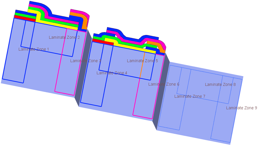
When the same material-orientation combination is defined at any stack-row in different stacks, a merged laminate object is created on the intersecting zones. After merging, the laminate objects are arranged such that the largest laminate object is placed at the bottom, as shown in the following graphic:
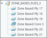
8. In the Laminate Tree, expand the ZONE_BASED_PLIES_3 group to see the created laminate objects as shown in the following graphic:

9. In the Composite Tree, expand the ZONE_BASED_PLIES_3 group to see the features of the laminate objects as shown in the following graphic:
10. On the Laminate Tree, click Laminate Manager. The Laminate Tree opens in the Laminate Manager mode.
Laminate Manager. The Laminate Tree opens in the Laminate Manager mode.11. Increase the width of the Zones column to see the names of the zones. You can also move the mouse pointer over a cell in the zones column to see the names of the zones in the tooltip.
The merged laminate objects and their zones are displayed as follows:
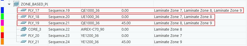
The laminate objects are created in the order of the sets specified in the Plies from Zones dialog box. When the Ignore stack row option is selected, similar laminate objects merge when they are created in the adjacent or intersecting zones, and they can be located in the same or different rows in their stacks. • Since UE1000_36,0 is defined at the same second row in Stack 1 and Stack 2, a merged ply is created on Laminate Zone 7 and Laminate Zone 8. • Since QE1000_36,45 is defined at the same third row in Stack 2 and Stack 3, a merged ply is created on Laminate Zone 8 and Laminate Zone 9. • The same material-orientation combination QE1000_36,0 is defined at different rows in Stack 1, Stack 2, and Stack 3, a merged ply is created on Laminate Zone 7, Laminate Zone 8, and Laminate Zone 9. |
12. On the Laminate Tree, click Laminate List.
Laminate List.13. To save the changes and close the Composite tab, click OK.
OK.