About Bend Lines
You can use bend lines to determine the location and shape for the bend geometry in your sheet metal parts. The behavior of the bend geometry is determined by the bend line location, the bend angle, and the fixed geometry. Bend lines are reference points for calculating developed length and creating bend geometry.
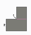
The following figure shows a typical bend line.
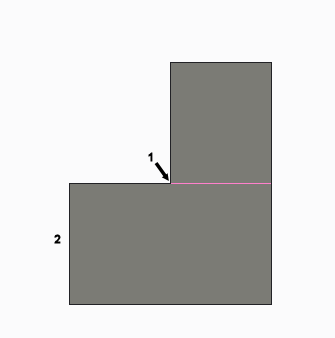
1. Bend line
2. Fixed geometry
In the following figures, the material is bent on the other side of the bend line ( ).
).
 ).
).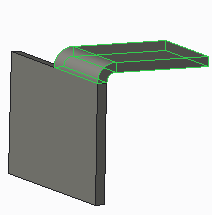 | 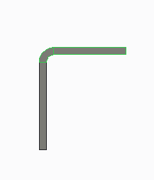 |
In the following figures, the material is bent up to the bend line ( ).
).
 ).
).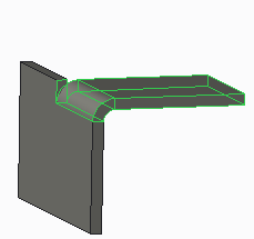 | 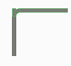 |
In the following figures, the material is bent on both sides of the bend line ( )
)
 )
)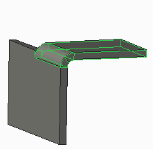 | 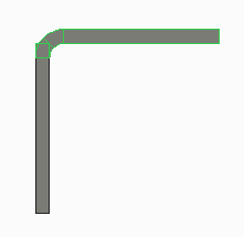 |
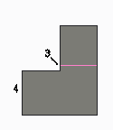
You can adjust the bend line to make the resulting bend geometry coplanar with the side of the sheet metal. Make sure any added bend relief does not exceed the developed length of the bend.
Non-coplanar Surfaces | Coplanar Surfaces |
|---|---|
  |   |
BLA = L - ( R + T ) | |
Where: BLA = Bend line adjustment L = Developed length of the bend (determined from a bend table or formula) R = Inside radius of the bend T = Thickness of the sheet metal RL = Relief length ( = cutback length in rip relief) | |
1. Original bend line
2. Fixed geometry and bend side
3. Adjusted bend line
4. Fixed geometry and bend side
Keep in mind that a bend line used to define the bend in the Bend tool is not necessarily the bend line used for manufacturing. For the bend line to coincide with the bend line used in manufacturing, you must define the bend using the  , bend material on both sides of bend line, command. When you use other options, the bend line coincides with either of the tangent edges between the bend area and the adjacent planar area. An axis is created for the manufacturing bend line in the Unbend and Flat Pattern tools.
 , bend material on both sides of bend line, command. When you use other options, the bend line coincides with either of the tangent edges between the bend area and the adjacent planar area. An axis is created for the manufacturing bend line in the Unbend and Flat Pattern tools.