Adding a New Pipe Size
Use the sample files provided here when working in this exercise. It is recommended that you set up piping data before you start working with the tutorial.
Workflow
1. Define a new pipe size.
2. Do one of the following:
◦ Define data for a pipe with a bend.
◦ Define data for a pipe with a miter joint.
3. Define a new pipe size in the Auto-Selection file.
4. Create a pipe segment with the new size.
Define a New Pipe Size
1. In the piping_data folder, double-click the master_catalog folder, double-click the pipe folder, and open the pipe_steel.csv file.
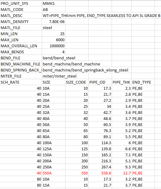
2. Insert a row and add the following values to the catalog file:
|
SCH_RATE
|
SIZE
|
SIZE_CODE
|
PIPE_OD
|
PIPE_THK
|
END_TYPE
|
|
40
|
550A
|
550
|
558.8
|
12.7
|
PE,BE
|
In the following image, new pipe size values are in red:
3. Save and close the Pipe master catalog file.
4. Do one of the following:
Define Data for a Pipe with a Bend
1. Click the bend folder and open the bend_steel.csv file.
2. Type the following values:
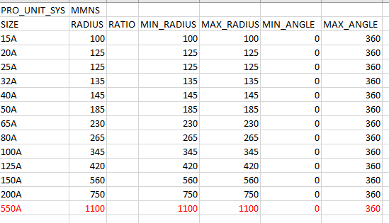
SIZE | RADIUS | RATIO | MIN_RADIUS | MAX_RADIUS | MIN_ANGLE | MAX_ANGLE |
550A | 1100 | 1100 | 1100 | 0 | 360 |
In the following image, new bend values are in red:
3. Save and close the Bend file.
4. Click the bend_machine folder and open the bend_springback_elong_steel.csv file.
5. Type the following values:
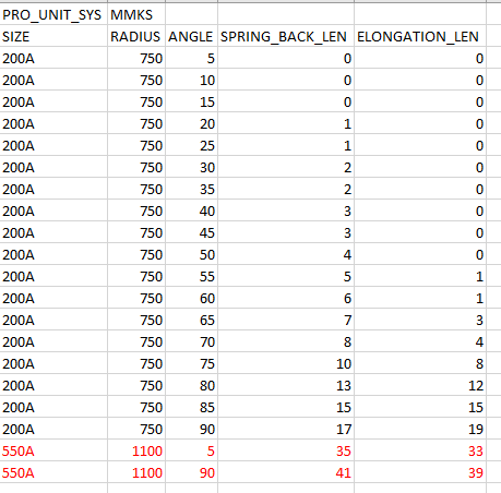
SIZE | RADIUS | ANGLE | SPRING_BACK_LEN | ELONGATION_LEN |
550A | 1100 | 5 | 35 | 33 |
550A | 1100 | 90 | 41 | 39 |
In the following image, new spring back and elongation values are in red:
6. Save and close the Bending Spring Back and Elongation file.
7. In the bend_machine folder, open the bend_machine.csv file.
8. Type the following values:
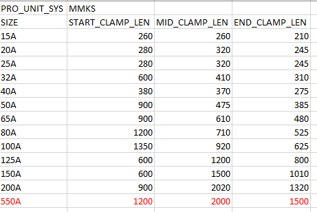
SIZE | START_CLAMP_LEN | MID_CLAMP_LEN | END_CLAMP_LEN |
550A | 1200 | 2000 | 1500 |
In the following image, new bend manufacturing values are in red:
9. Save and close the Bend Machine file.
Define Data for a Pipe with a Miter Joint
1. Click the miter folder and open the miter_steel.csv file. Type the following values:
SIZE | RADIUS | MIN_ANGLE | MAX_ANGLE | CUT_NUMBER |
550A | 559 | 0 | 30 | 1 |
550A | 559 | 30 | 60 | 2 |
550A | 559 | 60 | 90 | 3 |
In the following image, new miter values are in red:
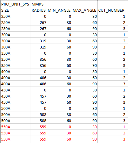
2. Save and close the Miter file.
Define a New Pipe Size in the Auto-Selection file
1. Open the piping folder and set the piping_assembly folder as the Working Directory.
2. Open manifold_skid.asm.
3. Click >  Piping. The Piping tab opens.
Piping. The Piping tab opens.4. Click  Spec DB. The Define Piping Specification dialog box opens.
Spec DB. The Define Piping Specification dialog box opens.5. Click  . The Open File dialog box opens.
. The Open File dialog box opens.6. Double-click ms_asfile.ptd. The selected file populates the Define Piping Specification dialog box.
7. In the Schedule box, select 40.
8. Click  to edit the pipe sizes.
to edit the pipe sizes.9. Select 550A and click OK to add the new pipe size.
10. Select the Allow Bend and Allow Miter check boxes.
11. Click  to add the displayed specification record to the Auto-Selection file.
to add the displayed specification record to the Auto-Selection file.12. Click  to save the file.
to save the file.13. Close the Define Piping Specification dialog box.
Create a Pipe Segment with the New Size
1. Click Route Pipe.
Route Pipe.2. Select a pipe segment in the graphics window. A warning message opens.
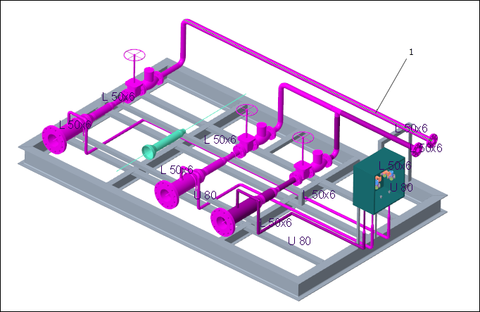
1. Pipe segment
3. Click Confirm in the warning message.
4. Click Set Start. The Define Start dialog box opens.
Set Start. The Define Start dialog box opens.5. Click > >  Coordinate System.
Coordinate System.6. Select ASM_DEF_CSYS at the corner of the skid as the Reference.
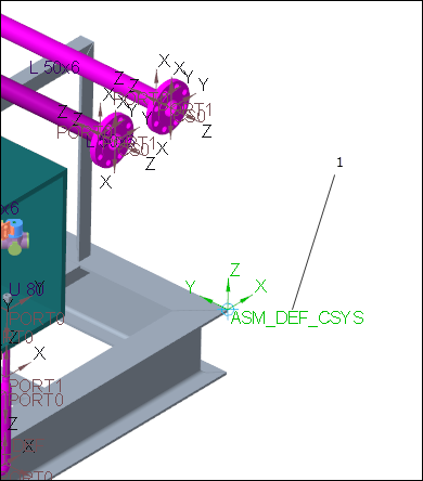
1. Coordinate system
7. In the Size box, select 550A.
8. Click OK.
9. Click >  Extend. The Extend dialog box opens.
Extend. The Extend dialog box opens.10. Drag a dragger handle along the z-axis.
11. Click OK. The new pipe segment of the size 550A is created.

1. New pipe segment