Offset Surface Methods—Recommendations
This topic contains recommendations for the following offset methods:
• Example
Normal to Surface
The following are recommendations for creating a successful Normal to Surface offset:
• Try the Normal to Surface offset method first.
◦ If it succeeds, this method provides you with a result faster.
◦ If it doesn’t succeed, it will give you a very quick initial overview of potential problematic surface areas.
The following error messages might indicate geometric problems that need to be fixed manually before performing any offset operation:
▪ Offset cannot be constructed at the highlighted edges/vertices.
This might indicate a problem with the edge or the existence of a small sliver surface at the edge. Check and fix the edge geometry.
▪ Offset cannot be constructed at the highlighted surface.
This might indicate a problem with surface connections. Try to fix it, or offset the surface individually.
Automatic Fit and Controlled Fit
• If Normal to Surface fails, use Automatic Fit. The Automatic Fit method automatically calculates the best directions to translate the surfaces such that they appear as original ones. However, this method does not guarantee a uniform offset normal to surfaces. If the results of Automatic Fit are not satisfactory, you can use Controlled Fit to aid in calculation.
• It is recommended that you use Automatic Fit and Controlled Fit with convex geometry only. These methods involve scaling of geometry. For non-convex geometry, the offset distance may vary, as shown in the following figure.
Offsetting complex surface shapes
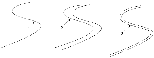
1. Original surface
2. Resulting surface using Automatic Fit
3. Resulting surface using Normal to Surface
• When you use Automatic Fit or Controlled Fit to create an offset, the system attempts to make the distance between the original and the offset quilt no less than the input value.
• The location of the coordinate system that you select when using Controlled Fit affects how the quilt is scaled. In the following illustration, the offset quilt is created using Controlled Fit with the translation restricted along the x- and y-axes. In Illustration a, scaling is with respect to the CS0 coordinate system, while scaling is with respect to the CS3 coordinate system in Illustration b. Note that the location of the coordinate system determines which edges remain coplanar.
◦ Illustration a. Offset created using CS0
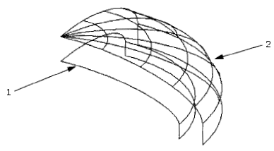
1. Original quilt
2. Offset quilt
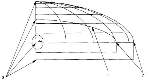
1. Coplanar vertices, translation is not allowed along the x-axis
2. Original quilt
3. Coplanar vertices, translation is not allowed along the y-axis
The edges and vertices on the plane that passes through the origin of the CS0 coordinate system (the yz- and xz-planes, respectively) remain fixed. This is because translation is not allowed along the x- and y-axes.
◦ Illustration b. Offset created using CS3
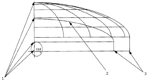
1. Coplanar vertices, translation is not allowed along the x-axis
2. Original quilt
3. Coplanar vertices, translation is not allowed along the y-axis
The edges and vertices on the plane that passes through the origin of the CS3 coordinate system (the yz- and xz-planes, respectively) remain fixed. This is because translation is not allowed along the x- and y-axes.
Example
The following figure illustrates the difference in the offset geometry created through the Normal to Surface, Controlled Fit, and Automatic Fit methods. In this example, the Controlled Fit method allows you to select the coordinate system for translation and restrict the translation of the scaled geometry along the y-axis such that the resulting quilt terminates at the same level as the original quilt. Note that the resulting radius of curvature differs depending on the offset type used.
Using different offset methods
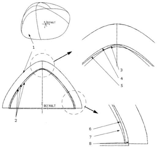
1. Original quilt
2. Offsets from the original quilt
3. Using Normal to Surface
4. Using Controlled Fit
5. Using Automatic Fit
6. Using Controlled Fit
7. Using Normal to Surface
8. Using Automatic Fit
Rolling Ball
If the Normal to Surface offset does not lead to the desired result, you can use the Rolling Ball method. It is suitable for the following cases:
• When surfaces contain high curvature areas (the curvature radius is smaller than the offset value).
• When the offset leads to complex topology changes and self-intersections during offset.
The following are recommendations for creating a successful Rolling Ball offset:
•  No Preview
No PreviewWhen invoking the Rolling Ball offset option, use No Preview. When the feature preview is turned off, it saves time by allowing you to adjust all the feature settings before the geometry is calculated.
No Preview. When the feature preview is turned off, it saves time by allowing you to adjust all the feature settings before the geometry is calculated.When you switch the Offset Method to the Rolling Ball option, the preview mode automatically changes to No Preview.
No Preview.When you work in  Attached Preview or
  Unattached Preview mode, calculating the geometry could take time.
Attached Preview or Unattached Preview mode, calculating the geometry could take time.•  Verify
VerifyWhen you preview a feature by clicking Verify, the system informs you if there are issues with the geometry:
Verify, the system informs you if there are issues with the geometry:◦ Feature succeeds
If the feature succeeds yet contains issues, for example, it contains singularity points, the issues are listed in the Notifications dialog box.
◦ Feature fails
If the feature fails, the issues are listed in the Troubleshooter dialog box.
For each issue, the arrows point to the previously created preview geometry.
• Maintain boundary shape
This option is sensitive to the smoothness of the boundaries. Avoid using the Maintain boundary shape option in following cases:
◦ The boundaries contain small edges or sharp corners.
◦ The boundaries contain high curvature areas.
◦ Walls or side surfaces at the boundary of the quilt are smaller than the offset value.
To prevent unexpected results, before you offset a surface that contains small edges at the boundary, try replacing areas of small edges with a patch made of longer entities.
• Patching
Start to create a Rolling Ball offset with the Patching check box cleared.
If you choose to select the Patching check box on the Options tab, the recommended value of the Patch radius could be up to 100% of the Offset value on the Offset tab. The best values to start with might range from 5 through 25% of the offset value.
In cases where the Patching surfaces cannot be created, you might want to try the following options:
◦ Use a different patch radius value.
◦ Switch the patching type between Round and Droplet.
◦ Create a surface to surface round with a radius value larger than the offset value manually, before the Offset feature.
• Excluded surfaces
In cases where the result can only be achieved by specifying several excluded surfaces in the Special Handling collector, check the resulting geometry. It might contain self-intersecting surfaces.
For round surfaces that are excluded, it might be possible to manually create a surface to surface round first, with a radius value equal to the offset value. If this succeeds, these round surfaces can be removed from the excluded surfaces list.
• Accuracy
Work with the appropriate level of accuracy.
If you need to refine the accuracy, make slight changes, keeping the value at the same order of magnitude.
To edit the accuracy, click > >  Model Properties, and in the
Model Properties, and in theModel Properties dialog box, in the Accuracy row, click change to open the Accuracy dialog box.