To Create Floor 5 Axis Finish Sequences
Define Floor 5 axis finish sequences to machine wall surfaces in the pocket-shaped geometries.
Ensure that the active operation references a 5 axis Mill or Mill/Turn work center that has milling capability.
|
|
The  Floor 5 Axis Finish command with the Mill/Turn work center is available when you have both the Complete Machining and ModuleWorks-based Mold Machining licenses. Floor 5 Axis Finish command with the Mill/Turn work center is available when you have both the Complete Machining and ModuleWorks-based Mold Machining licenses. |
1. Click > Floor 5 Axis Finish in the High Speed Milling group. The Floor Finish tab opens.
Floor 5 Axis Finish in the High Speed Milling group. The Floor Finish tab opens.2. Click Tool Manager or select Edit Tools from the tool list box to open the Tools Setup dialog box and add a new cutting tool or change tool parameters. The tool list only includes tools that are valid for the step.
To show tools for the current step and the active head on the machine tool, set the INCLUDE_ALL_TOOLS_IN_LIST option to YES. |
The supported tools for this sequence are as follows:
◦ Ball Mill (default)
◦ Taper Ball Mill
◦ Barrel Lens
For Floor 5 axis finish, it is recommended to use holders or use a tool that is sufficiently long for automatic tilt to work properly. |
3. To preview the cutting tool and its orientation in the graphics window, click  Tool Preview next to the Tool list.
Tool Preview next to the Tool list.The Tool Preview button becomes available after you select a tool. |
Alternatively, right-click the graphics window and select the Tool Preview option on the shortcut menu. After you select a tool, the Tool Preview option is available on the shortcut menu of the graphics window.
To exit the tool preview, right-click the graphics window and select Cancel tool preview from the shortcut menu or click Tool Preview again.
Tool Preview again.4. To change the coordinate system that defines the orientation of the step, click the collector adjacent to  and select a coordinate system. If the operation coordinate system differs from the step coordinate system, right-click the collector for the following commands:
and select a coordinate system. If the operation coordinate system differs from the step coordinate system, right-click the collector for the following commands:◦ Default—Replaces the selected coordinate system with the default reference. The default is the orientation that is copied from the previous step or from the operation.
◦ Information—Displays the information of the selected coordinate system.
If your work center setup has two spindles, choose Main Spindle or Sub Spindle from the list, and select a coordinate system each for the main and sub spindle.
The sub spindle is available when you have both the Complete Machining and ModuleWorks-based Mold Machining licenses. After you specify a coordinate system for an NC sequence, it remains in effect until you change it. |
Alternatively, right-click the graphics window and select Orientation from the shortcut menu.
5. Define the options in the following tabs:
◦ Link
◦ Options
◦ Process
6. Click  to open a separate CL Data window.
to open a separate CL Data window.7. Click  to get a dynamic preview of the toolpath in the graphics window.
to get a dynamic preview of the toolpath in the graphics window.8. After you define the mandatory step elements, select a command for toolpath validation:
◦ To play the toolpath, click the arrow next to  and select .
and select .◦ To recompute the toolpath, click the arrow next to and select  .
.
and select .◦ To perform gouge checking against surfaces of the reference part, click the arrow next to and select  .
.
and select .◦ To view the simulation of material removal as the tool is cutting the workpiece, click the arrow next to and select  . The Material Removal tab with integrated simulation environment opens.
and select . The Material Removal tab with integrated simulation environment opens.9. Select one of the following options to complete the sequence:
◦ Click  to save the changes.
to save the changes.◦ Click  to pause the process and use one of the asynchronous tools or click
  to resume.
to pause the process and use one of the asynchronous tools or click to resume.◦ Click  to cancel the changes.
to cancel the changes.Reference Tab
Select the floor references and wall references. Define the pattern type and input for the guide curves.
Under Floor References, set the following options:
• Selection type—Select the floor surfaces or a previous step.
◦ Surface—Select individual surfaces or click Details and select surface sets from the graphics window. Right-click and select Remove to remove the surfaces.
Alternatively, right-click the graphics window. On the shortcut menu, select Floor surface and then select the required surfaces.
Click  to select the direction of the machining side. becomes available if you have selected quilt surfaces.
to select the direction of the machining side. becomes available if you have selected quilt surfaces.◦ Previous Step—Select the previous step that contains the surfaces you want to use as a floor surface.
Alternatively, right-click the graphics window. On the shortcut menu, select Floor References and then select the required step from the model tree.
Under Wall References, set the following options:
• Selection type—Select the wall surfaces or a previous step.
◦ Surface—Select individual surfaces or click Details and select surface sets from the graphics window. Right-click and select Remove to remove the surfaces.
Alternatively, right-click the graphics window. On the shortcut menu, select Wall surface and then select the required surfaces.
Click to select the direction of the machining side. is available if you have selected quilt surfaces.
to select the direction of the machining side. is available if you have selected quilt surfaces.◦ Previous Step—Select the previous step that contains the surfaces you want to use as a wall surface.
Alternatively, right-click the graphics window. On the shortcut menu, select Wall References and then select the required step from the model tree.
If same surfaces are selected for wall and floor, a toolpath is generated based on the intersection of surfaces. Such a toolpath may be unsuitable for all Pattern type options or all Input options. Hence, it is recommended to select different surfaces for wall and floor for an optimum toolpath. |
Wall and floor surface preferably should not be disjoint for optimum toolpath creation. |
Under Guide Curves, set the following options:
• Pattern type—Select the pattern of the toolpath.
◦ Offset from floor (default)—In the toolpath, slices are offset from the selected floor surfaces boundaries. The Input list is not available for this pattern type.
◦ Parallel to guide curves—In the toolpath, slices are created parallel to the guide curves according to the input provided.
The Input options are as follows:
▪ Longest edge (default)—Automatically detects the longest edge to use it as a guide curve.
▪ User defined—Select the curves or edges manually to use them as guide curves. The generated toolpath is based on these guide curves. You can select open or closed curves or a mix of these curves. You can also use Details to select the guide curves. This option is available when both floor and wall collectors are defined. The user-defined guide curves must lie on the machining surface.
If you select multiple floor surfaces, define a guide curve for all surfaces or select a guide curve that passes through all floor surfaces. |
Alternatively, right-click the graphics window. Select Pattern Type and then select the required option. Similarly, select Input and then select the required option.
Parameters Tab
Specify the required manufacturing parameters. You can also click  to copy parameters from an earlier step or click
  to edit parameters specific to Floor 5 axis finish. By default, the required parameters for the selected tool are defined by relations that you can modify from the Relations dialog box. For more information on parameters, see Wall 5 Axis Finish and Floor 5 Axis Finish Parameters
for Cut Depth and Allowances and Wall 5 Axis Finish and Floor 5 Axis Finish Parameters
for Cutting Motions.
to edit parameters specific to Floor 5 axis finish. By default, the required parameters for the selected tool are defined by relations that you can modify from the Relations dialog box. For more information on parameters, see Wall 5 Axis Finish and Floor 5 Axis Finish Parameters
for Cut Depth and Allowances and Wall 5 Axis Finish and Floor 5 Axis Finish Parameters
for Cutting Motions.
to copy parameters from an earlier step or click to edit parameters specific to Floor 5 axis finish. By default, the required parameters for the selected tool are defined by relations that you can modify from the Relations dialog box. For more information on parameters, see Wall 5 Axis Finish and Floor 5 Axis Finish Parameters
for Cut Depth and Allowances and Wall 5 Axis Finish and Floor 5 Axis Finish Parameters
for Cutting Motions.Alternatively, right-click the graphics window and select Parameters from the shortcut menu.
Clearance Tab
Define the tool retract, and the start and end points of the toolpath.
• Retract—Define the options for the tool retract.
◦ Type
▪ Automatic (default)—Toolpath automatically generates tool retracts. Hence, additional inputs such as Reference, Orientation, and Value are not applicable.
▪ Plane
▪ Cylinder
▪ Sphere
◦ Reference
◦ Orientation
◦ Value
• Start and End Points—Select the Start point and End point of the toolpath.
Axis Control Tab
Define the tool contact point, lead angle, and tilt angle settings.
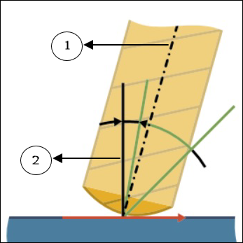
• Under Relative Contact Point Height on Tool Profile, set the following options:
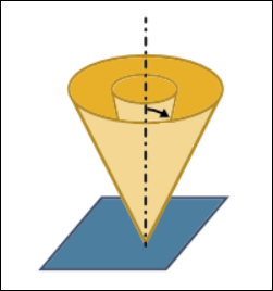
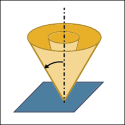
◦ Preferred height—Specify a preferred contact point on the tool where the tool is aligned tangentially on surface. Range is from 0 to 1, where:
▪ 0 represents the lower limit of minimum height.
▪ 1 represents the upper limit of maximum height.
Default value is 0.
Preferred height must be between Minimum height and Maximum height. |
◦ Minimum height—Specify the minimum height of the contact point on the tool where the tool can be aligned tangentially on a surface to avoid collisions. Range is from 0 to the Preferred height value. 0 represents the lower limit of minimum height.
Default value is 0.
◦ Maximum height—Specify the maximum height of the contact point on the tool where the tool can be aligned tangentially on a surface to avoid collisions. Range is from the Preferred height value to 1. 1 represents the upper limit of maximum height.
Default value is 0.6.
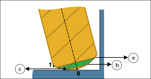
a - Defined Maximum height
b - Defined Minimum height
c - Preferred height
If collision is unavoidable in the specified range of the defined Minimum height and defined Maximum height, then the toolpath is trimmed. |
The defined maximum height represented by a, defined minimum height represented by b, and preferred height represented by c correspond to the ratio of lower limit of Minimum height and upper limit of Maximum height.
The following images show the lower limit of Minimum height represented by 0 and upper limit of Maximum height represented by 1 for supported tools that are considered during the toolpath calculations.
◦ Barrel Lens
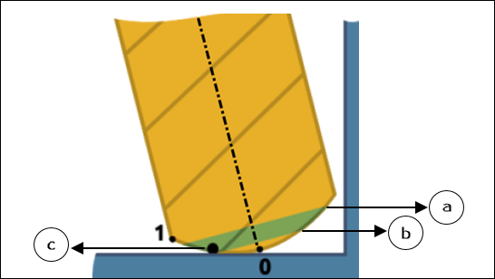
◦ Ball Mill
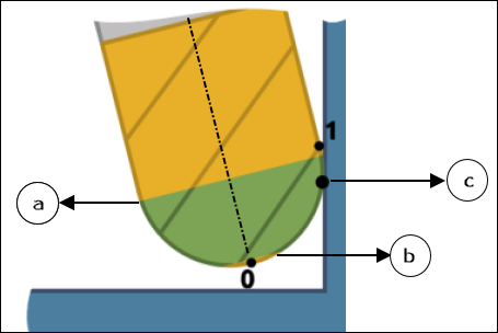
◦ Taper Ball Mill

• Under Lead Angle Relative to Surface Normal, set the following options:
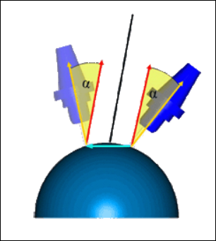
◦ Preferred lead angle—Specify a preferred angle between the tool axis and the surface normal. Surface normal is considered to be 0 degrees. Range is from greater than -90 degrees to less than 90 degrees.
Default value is 0 degrees.
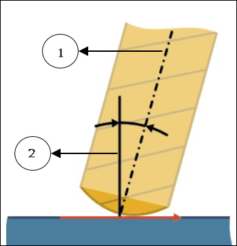
1. Tool axis
2. Surface normal
◦ Minimum lead angle—Specify the minimum lead angle at which the tool tilts to avoid collisions. Range is from greater than -90 degrees to less than the Preferred lead angle value.
Default value is -10 degrees.
1. Tool axis
2. Surface normal
◦ Maximum lead angle—Specify the maximum lead angle at which the tool tilts to avoid collisions. Range is from the Preferred lead angle value to less than 90 degrees.
Default value is 10 degrees.
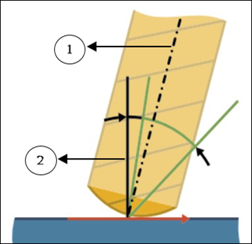
1. Tool axis
2. Surface normal
• Under Angle Range, define Maximum angle step. It is the maximum angle change allowed between two consecutive toolpath positions. Specify an angle greater than 0 degrees.
Default value is 3 degrees.
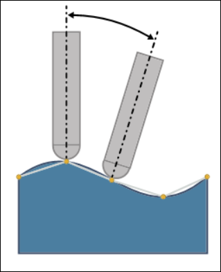
• Optionally, select the Tilt Angle Range checkbox to further limit the tool tilt according to the limitations of the machine. Define the following tilt options:
◦ Reference axis—Select Z axis or Custom axis.
Z axis is the default selection. It is the same z axis of the step orientation.
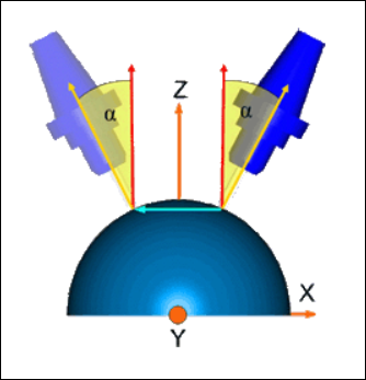
For Custom axis, select an axis around which the tool limits the tilt.
To flip the orientation of the axis according to your requirement, click .
.Maximum tilt angle and minimum tilt angle are considered with reference to the selected axis.
◦ Minimum tilt angle—Specify the minimum tilt angle from the reference axis towards the surface normal. Range is from 0 degrees to 180 degrees.
Default value is 0 degrees.
◦ Maximum tilt angle—Specify the maximum tilt angle from the reference axis towards the surface normal. Range is from 0 degrees to 180 degrees.
Default value is 180 degrees.
Link Tab
Define the lead and link types.
• Under Lead, specify the arc radius as a percentage of tool diameter or absolute value in the Lead Radius option. The default arc radius is 25% of the tool diameter.
• Under Links, define the connection type using the Large gaps option. Gaps are caused by the features of a machining surface shape and the selected toolpath type.
You can select the following types of large gaps:
◦ Clearance with blend spline—A tangential arc for connection between large gaps and for retracts of the tool.
◦ Retract to Clearance—Straight line connection with the tool retracting to the specified clearance area. The retracting tool uses retract defined in the Clearance tab.
Specify the threshold for determining the gaps in the Small gaps size option. Gaps larger than the defined threshold are considered as large gaps. You can specify the small gap size as an absolute value or in percentage of the tool diameter. The default is 20% of the tool diameter.
Check Surfaces Tab
Define the parts and surfaces that you want to degouge the toolpath against.
• Add reference parts—Select the checkbox to add reference part as a check surface for gouge-free toolpath.
• Check surfaces—Add surfaces, fixtures, or references that you want to degouge toolpath against in the Check surfaces collector.
• Check clearance—Specify the clearance on the selected check surfaces.
Default value is 0.
Check clearance is available only after you define the check surfaces. |
Alternatively, right-click the graphics window and select Check Surfaces.
• If no surfaces are selected as check surfaces, then the toolpath does not check for gouges or collisions. • The toolpath calculation performance varies based on the total number of defined check surfaces as the toolpath performs gouge checks and collision checks for all defined check surfaces. For best performance, select only the required check surfaces. |
Options Tab
Open a part or assembly to use as a cutting tool adapter. Alternatively, click  to copy cutting tool adapter from another step.
to copy cutting tool adapter from another step.Tool Motions Tab
To create a Goto Point tool motion, select Goto Point. For more information, see To Create a Goto Point Tool Motion.
To insert a CL command along the toolpath, select CL Command. For more information, see To Insert a CL Command for Tool Motions.
The Tool Motions tab is visible only when you define machining references. |
Process Tab
Use any of the following options for the machining step:
• Calculated Time—Click  to automatically calculate the machining time for the step. The Calculated Time box shows the time.
to automatically calculate the machining time for the step. The Calculated Time box shows the time.• Actual Time—Specify the machining time.
Properties Tab
Specify the name or comments for the step.
• Name—Displays the name of the step. You can type another name.
• Comments—Type the comments associated with the step in the text box or use the following options:
◦  —Read in an existing text file containing step comments and replace any current step comments.
—Read in an existing text file containing step comments and replace any current step comments.◦  —Insert the contents of an existing text file of step comments at the cursor location. Preserve any current step comments
—Insert the contents of an existing text file of step comments at the cursor location. Preserve any current step comments◦  —Save current step comments in a text file.
—Save current step comments in a text file.◦  —Accept the current step comments.
—Accept the current step comments.