To Create a Visual Field Feature
Create a Visual Field feature that contains one or more cones of vision. It can contain a combination of cones from a direct view, like a driver looking through a window, and a reflection view, like a driver looking at the reflection in a mirror.
1. Click >  Visual Field. The Visual Field tab opens.
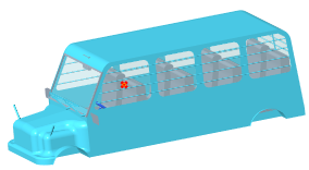
Visual Field. The Visual Field tab opens.2. To define the location of the driver’s eyes, make sure the Eye point collector is active, and select a datum point or a coordinate system. This is the vertex of the cone of vision.
3. Define parameters of the cone of vision, depending on whether the view is direct or reflection:
◦ Direct
a. Under Cone Type, click  Direct.
Direct.b. To define the outer contour of the cone, click the Look at or through collector, and select a body, a quilt, or a part. This item represents the object to look through, like a window, or to look at, like an instrument panel.
In the example, the front windshield is selected.

◦ Reflection
a. Under Cone Type, click  Reflection.
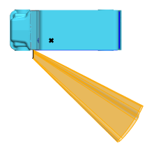
Reflection.b. To define the mirror that will be the start of the cone, click the Mirror collector, and select a quilt. All the surfaces of the quilt must be tangent.
In the example, the left side mirror is selected.
Side view:

Top view:
The resulting cone might not include the entire mirror. Only the portions of the mirror that are in the direct line of sight of the eye point are included.
For example, in the case of a convex mirror, the resulting cone is bounded by the farthest place that the eye point can see. The portions of the mirror that are out of the line of sight are not included.
Convex mirror:

Top view:

1. Portion not included in the cone
Front view:

1. Portion not included in the cone
c. To adjust the mirror angle:
i. To rotate the mirror in the first direction, click the Rotation 1 collector, and select an axis, axis of a coordinate system, intent axis, linear edge, or linear curve about which to rotate the mirror.
ii. Type an angle in degrees for the mirror to rotate about the axis.
iii. To rotate the mirror in the second direction, click the Rotation 2 collector, and repeat the previous two steps.
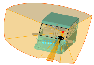
4. For a direct view, to identify obstructions within the contour of the cone, click the Obstructing objects collector, and select bodies, quilts, and components (parts or sub-assemblies). These decrease the cross-sectional area of the cone.
In the example, the steering wheel is selected as an obstructing object. Notice the projection of the steering wheel at the bottom of the cone.

This is the same example viewed from the front.
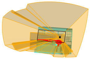
5. For a direct view, to exclude objects from being considered obstructions and treat them as if they are not obstructing, click the Excluded objects collector, and select bodies, quilts, and components (parts or sub-assemblies).
For example, if the entire bus is selected as an obstructing object, the right and left marker poles are removed from the bottom left and right of the cone.
The steering wheel and windshield wipers are selected as excluded objects. They are treated as if they are not obstructions, and they are not removed from the cone.
6. To define the view distance between the eye point and the imaginary spherical base of the cone, under View Distance, select one of the following options:
◦  By Value, and then type a distance value.
By Value, and then type a distance value.◦  By Reference, and then select a datum point, vertex, coordinate system, surface, plane, quilt, or body.
By Reference, and then select a datum point, vertex, coordinate system, surface, plane, quilt, or body.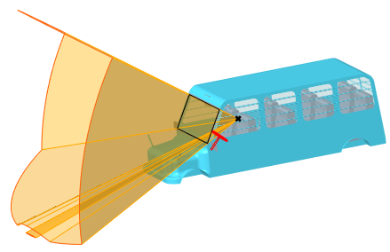
7. Optionally, to add another cone to the Visual Field feature, click the Cones tab, click Add new, and repeat steps 2–6 to define the new cone.
8. Click  OK.
OK.
OK.