Moving Components in ECAD Assemblies
You can use the Move Component tool to move selected components dynamically or by dimensions. Components are selected either before or after entering the Move Component tool. When you switch between the 2 types of move methods, the new move always applies to the original location of the components. Both types of move, create the same type of Move Component feature that does not store the dimensions used for creating the feature.
|
|
Any change made to a component through Collaboration or Get Changes will automatically remove this component as a reference from any Move Component feature. When this component was the only reference of the Move Component feature, the feature itself is automatically deleted.
|
You can select parts and subassemblies only from the active ECAD Assembly, and all components must be on the same level.
|
|
You can use the Move Component tool to move components only when the board is not flexible. When a board is not flexible, the  icon appears at the bottom of the main window. icon appears at the bottom of the main window. |
When you redefine a Move Component feature, the move type is set automatically to dynamic. The calculated 6DOF dimensions appear in the graphics area and Move tab.
Before you move components it is recommended to set the options below for updating references.
Updating References
Board level features that reference geometry of moved components are updated on regeneration. For best performance it is recommended to do the following:
• Set the copied_feat_refs_update_state configuration option to no_dependency.
• Set the Feature references to backup to References to other models in the Reference Creation Control dialog box. To access the dialog box, select the board part, right-click and select > .
Using Dynamic Move
1. In an open ECAD Assembly, click > > . The Move Component tab opens.
2. Select the components to move either individually or using box selection. The components appear in the References tab Move components collector.
3. Click Dimensions. The Dimensions tab opens. You can use the dragger or type a value in the required box. When you move the dragger, the Translation and Rotation values appear in the appropriate box.
4. To change the Move feature name, click Properties.
5. Click  .
.
 .
.Using Move by Dimension
1. In an open ECAD Assembly, click > > . The Move Component tab opens.
2. Select the components to move either individually or using box selection. The components appear in the References tab Move components collector.
3. Click Dimensions. The Dimensions tab opens.
4. Click the References collector and select a reference on the component being moved and select a reference from the assembly. You can define references for a linear or angular move.
5. To set the distance or angle between the references, type a number in the Value box or select from the list of values.
6. Repeat steps 4 and 5 to create up to 3 linear or angular dimension steps. When you have more than one linear dimension, they must be non-parallel. Once you create an angular dimension, you cannot create additional dimension steps.
7. To change the Move feature name, click Properties.
8. Click  .
.
 .
.Deleting Move Component Features
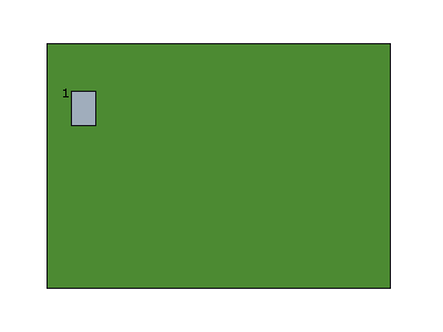
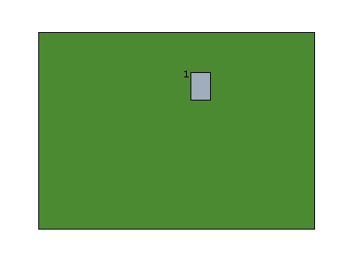
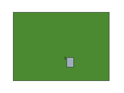
After you move a component and a Move Component feature is created, you can delete the feature. Only the dimension of the deleted feature are removed. Dimensions from other Move Component features still apply. See the examples below.
• The original position of the component on the board.

1. Component
• The first Move Component feature moves the component to a new location on the board.

1. Component
• The second Move Component feature moves the component to a different location on the board.

1. Component
• In the figure below, the first Move Component feature was deleted.

1. Component
 Dynamic Move
 Move by Dimension