To Create HSM 5 Axis Swarf Finish Step
Define a 5-axis Swarf finishing sequence to machine parts with steep walls, beveled edges, or tapered surfaces using the side of the cutting tool.
Ensure that the active operation references a 5 axis Mill or Mill/Turn work center.
|
|
The  HSM 5 Axis Swarf Finish command with the Mill/Turn work center is available when you have both the Complete Machining and ModuleWorks-based Mold Machining licenses. HSM 5 Axis Swarf Finish command with the Mill/Turn work center is available when you have both the Complete Machining and ModuleWorks-based Mold Machining licenses. |
1. Click Mill and then click HSM 5 Axis Swarf Finish in the High Speed Milling group. The HSM Swarf Finish tab opens.
HSM 5 Axis Swarf Finish in the High Speed Milling group. The HSM Swarf Finish tab opens.2. Click  Tool Manager or select
  Edit Tools from the Tool list to open the Tools Setup dialog box and add a new cutting tool or change tool parameters. The tool list only includes tools that are valid for the step.
Tool Manager or select Edit Tools from the Tool list to open the Tools Setup dialog box and add a new cutting tool or change tool parameters. The tool list only includes tools that are valid for the step.To show tools for the current step and the active head on the machine tool, set the INCLUDE_ALL_TOOLS_IN_LIST option to YES. |
The supported tools for this sequence are as follows:
◦ End Mill (default)
◦ Ball Mill
◦ Bull Mill
◦ Milling
Alternatively, right-click in the graphics window and select Tools.
3. To preview the cutting tool and its orientation in the graphics window, click  Tool Preview next to the Tool list.
Tool Preview next to the Tool list.The Tool Preview button becomes available after you select a tool. |
Alternatively, right-click the graphics window and select the Tool Preview option on the shortcut menu. After you select a tool, the Tool Preview option is available on the shortcut menu of the graphics window.
To exit the tool preview, right-click the graphics window and select Cancel tool preview from the shortcut menu or click Tool Preview again.
Tool Preview again.4. To change the coordinate system that defines the orientation of the step, click the collector adjacent to  and select a coordinate system. If the operation coordinate system differs from the step coordinate system, right-click the collector for the following commands:
and select a coordinate system. If the operation coordinate system differs from the step coordinate system, right-click the collector for the following commands:◦ Default—Replaces the selected coordinate system with the default reference. The default is the orientation that is copied from the previous step or from the operation.
◦ Information—Displays the information of the selected coordinate system.
If your work center setup has two spindles, choose Main Spindle or Sub Spindle from the list, and select a coordinate system each for the main and sub spindle.
The sub spindle is available when you have both the Complete Machining and ModuleWorks-based Mold Machining licenses. After you specify a coordinate system for an NC sequence, it remains in effect until you change it. |
Alternatively, right-click the graphics window and select Orientation from the shortcut menu.
5. Select a synchronization strategy from the Synchronization Strategy list. These strategies define preferences for various elements to achieve the desired swarf toolpath.
◦ Automatic (default)—Create toolpath automatically on swarf surfaces with automatic tool orientation based on input definitions.
This strategy requires minimum input definitions such as swarf surfaces only.
Optionally, you can select other references.
◦ Synchronize tilt curves—Create toolpath on swarf surfaces. The toolpath is aligned with the defined tilt curve references that lie on the swarf surfaces.
This strategy requires input definitions such as swarf surfaces and tilt curves.
Optionally, you can select other references.
◦ Synchronize guide curves—Create toolpath based on guide curves. The tool follows the upper and lower guide curves by connecting the corresponding points on the curves to create the toolpath.
This strategy requires input definitions such as upper and lower guide curves references.
Optionally, you can select other references.
◦ Shortest distance—Create toolpath using the shortest distance between the upper and lower guide curves or edges to align the tool with the curves. Use this strategy to machine flat shaped surfaces with sharp corners having unequal lengths of surface edges.
This strategy requires input definitions such as swarf surfaces. The Fanning distance value is predefined.
Optionally, you can select other references.
◦ Iso curves—Create toolpath that follows the isoline of the selected geometry and is placed parallel to the isoline.
This strategy requires input definitions such as swarf surfaces.
Optionally, you can select other references.
◦ Normal to guide curves—Create toolpath by projecting normals from the lower guide curve to intersect the upper guide curve. The tool is oriented normal to the guide curve.
This strategy requires input definitions such as swarf surfaces.
Optionally, you can select other references.
6. Define the options in the following tabs:
◦ Links
7. Click  to open a separate CL Data window.
to open a separate CL Data window.8. Click  to get a dynamic preview of the toolpath in the graphics window.
to get a dynamic preview of the toolpath in the graphics window.9. After you define the mandatory step elements, select a command for toolpath validation:
◦ To play the toolpath, click the arrow next to  and select .
and select .◦ To recompute the toolpath, click the arrow next to and select  .
.
and select .◦ To perform gouge checking against surfaces of the reference part, click the arrow next to and select  .
.
and select .◦ To view the simulation of material removal as the tool is cutting the workpiece, click the arrow next to and select  . The Material Removal tab with integrated simulation environment opens.
and select . The Material Removal tab with integrated simulation environment opens.10. Select one of the following options to complete the sequence:
◦ Click  to save the changes.
to save the changes.◦ Click  to pause the process and use one of the asynchronous tools or click
  to resume.
to pause the process and use one of the asynchronous tools or click to resume.◦ Click  to cancel the changes.
to cancel the changes.References Tab
The options on the References tab are available based on the selected synchronization strategy. |
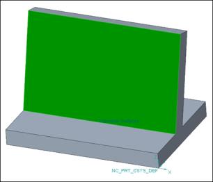
• Swarf References—Define the following options:
◦ Selection type—Select a swarf surface or a previous step.
▪ Surface—Select individual surfaces or click Details and select surface sets from the graphics window. Right-click and select Remove to remove the surfaces.
Alternatively, right-click the graphics window. On the shortcut menu, select Swarf References and then select the required surfaces.
Click  to select the direction of the machining side. is available if you have selected quilt surfaces.
to select the direction of the machining side. is available if you have selected quilt surfaces.Selection of disjoint surfaces is supported.
▪ Previous step—Select the previous step that contains the surfaces you want to use as a swarf surface.
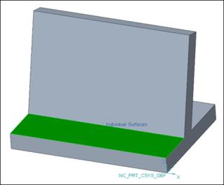
• Floor References—Define the following options:
◦ Selection type—Select a floor surface or a previous step.
▪ Surface—Select individual surfaces or click Details and select surface sets from the graphics window. Right-click and select Remove to remove the surfaces.
Alternatively, right-click the graphics window. On the shortcut menu, select Floor References and then select the required surfaces.
▪ Previous step—Select the previous step that contains the surfaces you want to use as a floor surface.
• Selection of the swarf surface is mandatory for all strategies except Synchronize guide curves. • Selection of the floor surface is optional for all strategies. |
• Tool Tilt References—Select the tilt curves.
◦ Tilt curves—Select one or more tilt curves lying on the swarf surface. Alternatively, click Details and select the required chains. The tool aligns automatically with the defined tilt curves at the intersection of the tilt curve with the lower curve or lower edge of the swarf surface.
Alternatively, right-click the graphics window. On the shortcut menu, select Tilt Curves, and then select the required chains.
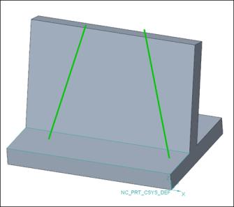
• This option is available only for the Synchronize tilt curves strategy. • The defined tilt curve must be on the swarf surface. • The defined tilt curve must intersect both upper and lower guide curves or upper and lower edges of a swarf surface. |
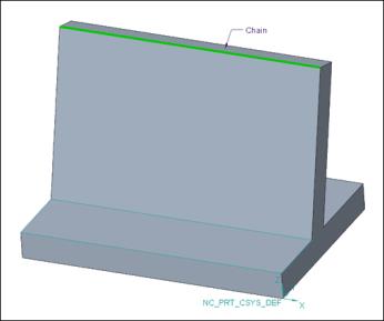
• Guide Curves—Select the guide curves.
◦ Upper—Select the upper edge of the swarf surface or select any curve or edge. Alternatively, click Details and select the required chains.
The upper guide curve defines the upper contact point of the tool.
Alternatively, right-click the graphics window. On the shortcut menu, select Upper Guide Curve, and then select the required chains.
◦ Lower—Select the lower edge of the swarf surface or select any curve or edge. Alternatively, click Details and select the required chains.
The lower guide curve defines the lower contact point of the tool.
Alternatively, right-click the graphics window. On the shortcut menu, select Lower Guide Curve and then select the required chains.
Click to select the direction of the machining side.
to select the direction of the machining side.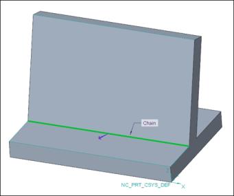
• The Guide Curves option is available for all strategies except the Automatic strategy. • The tool orientation depends on the position of the defined upper and lower guide curve. The tool always orients in such a way that the cutting portion of the tool is oriented towards the lower guide curve. • The machining side directional arrow is available only for the lower guide curve under the following conditions: ◦ The upper guide curve is defined. ◦ The Synchronize guide curves strategy is selected. |
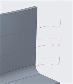
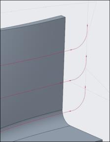
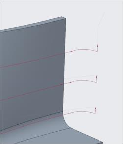
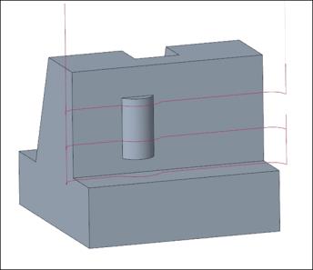
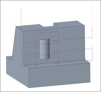
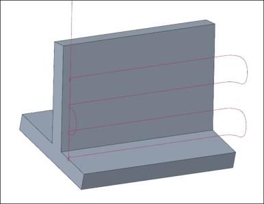
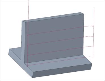
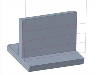
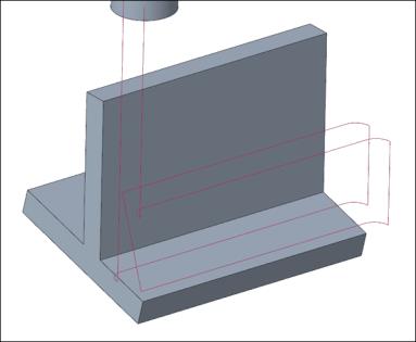
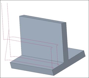
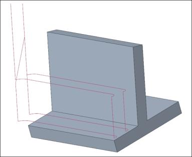
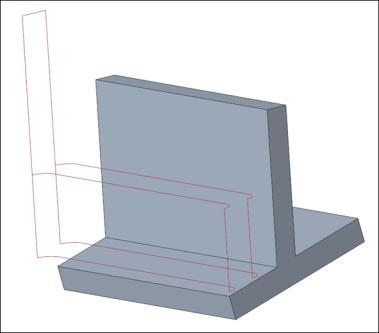
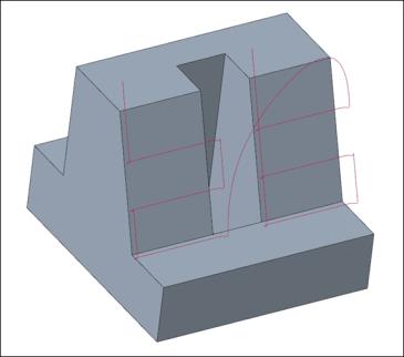
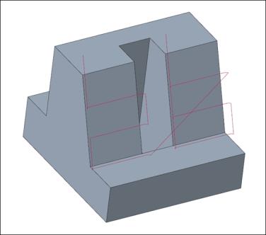
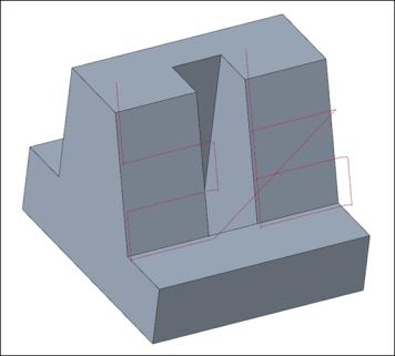
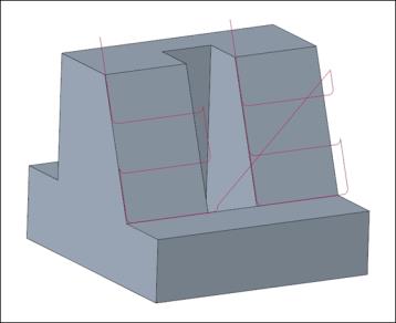
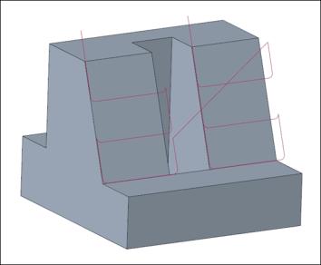
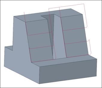
• Fanning distance—Enter the distance to smooth the tool axis transition between the upper and lower guide curves.
The smoothness of the tool axis transition improves with the optimal higher value.
Fanning distance value specified as 5:
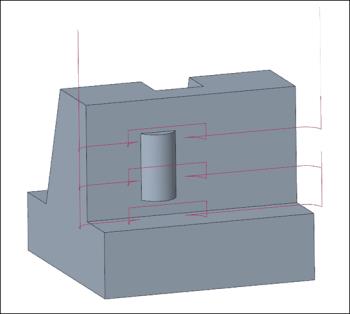
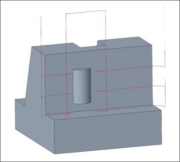
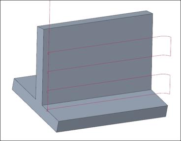
Fanning distance value specified as 12:
This option is available only for the Shortest distance strategy. |
Parameters Tab
Specify the required manufacturing parameters. You can also click  to copy parameters from an earlier step or click
  to edit parameters specific to Rotary finish sequence. By default, the required parameters for the selected tool are defined by relations that you can modify from the Relations dialog box.
to copy parameters from an earlier step or click to edit parameters specific to Rotary finish sequence. By default, the required parameters for the selected tool are defined by relations that you can modify from the Relations dialog box.Alternatively, right-click the graphics window and select Parameters from the shortcut menu.
For more information on parameters specific to the swarf high speed milling sequence, see Swarf Finishing HSM Parameters.
Clearance Tab
Define the retract type and start and end points for the step toolpath.
• Retract—Select the Automatic (default), Plane, Cylinder, or Sphere retract type.
• Start and End Points—Specify the Start point and End point of the toolpath.
Alternatively, right-click the graphics window and select Start Point and End Point from the shortcut menu to select start and end points of the toolpath.
Links
Define the lead and link types for gaps along the cuts. Also define the links between cuts, between passes, or between regions.
• Lead—Specify the following options:
◦ Lead-in—Specify an entry motion to the machining surfaces.
◦ Lead out—Specify an exit motion from the machining surfaces.
◦ Lead radius—Specify the arc radius as a percentage of tool diameter or absolute value.
The default arc radius is 25% of the tool diameter.
The following lead-in and lead-out types are available:
◦ Automatic arc (default)—Consists of two splines. The first spline enters or exits the surface tangentially to the surface normal direction. The second spline uses the tool axis tilting orientation to connect tangentially to the plunge or retract motion.
◦ Vertical tangential arc—Connects the start and end of the toolpath with the tangential arc separately. The orientation of this tangential arc is normal to the machining plane.
◦ Horizontal tangential arc—Connects the start and end of the toolpath with the tangential arc separately. The orientation is along the machining plane.
• Gaps Along Cut—Specify the connection type.
Gaps along the cut are caused by the obstructing geometry on the machining surface.
◦ Small gaps and Large gaps—Select one of the following options:
▪ Blend spline—Creates a tangential arc connection between the gap edges. The cut feed rate value is applied for this connection type.
This is the default option for Small gaps.
▪ Direct—Creates a straight-line connection on the shortest path between the gap edges. The cut feed rate value is applied for this connection type.
▪ Follow surface—Creates a connection that follows geometry on the gap edges. The cut feed rate value is applied for this connection type.
▪ Retract to clear distance—Creates a straight-line connection between the gap edges with the tool retracting to the specified clear distance.
This is the default option for Large gaps.
▪ Retract to rapid distance—Creates a straight-line connection between the gap edges with the tool retracting to the specified rapid distance.
▪ Retract to clearance—Creates a straight-line connection between the gap edges with the tool retracting to the specified clearance area.
◦ Small gaps threshold—Specify the threshold for determining whether to use small gaps or large gaps. The default value is 20.
• Links Between Cuts—Specify the connection between consecutive cuts.
◦ Small moves and Large moves—Select one of the following options:
▪ Blend spline—Creates a tangential arc connection between the consecutive cuts. The cut feed rate value is applied for this connection type.
This is the default option for Small moves.
▪ Direct—Creates a straight-line connection on the shortest path between the consecutive cuts. The cut feed rate value is applied for this connection type.
▪ Follow surface—Creates a connection that follows geometry on the consecutive cuts. The cut feed rate value is applied for this connection type.
▪ Retract to clear distance—Creates a straight-line connection between the consecutive cuts with the tool retracting to the specified clear distance.
This is the default option for Large moves.
▪ Retract to rapid distance—Creates a straight-line connection between the consecutive cuts with the tool retracting to the specified rapid distance.
▪ Retract to clearance—Creates a straight-line connection between the consecutive cuts with the tool retracting to the specified clearance area.
◦ Small moves threshold—Specify the threshold for determining whether to use small moves or large moves. The default value is 10.
• Links Between Passes—Specify the connection between consecutive passes.
◦ Small moves and Large moves—Select one of the following options:
▪ Blend spline—Creates a tangential arc connection between the consecutive passes. The cut feed rate value is applied for this connection type.
This is the default option for Small moves.
▪ Direct—Creates a straight-line connection on the shortest path between the consecutive passes. The cut feed rate value is applied for this connection type.
▪ Follow surface—Creates a connection that follows geometry on the consecutive passes. The cut feed rate value is applied for this connection type.
▪ Retract to clear distance—Creates a straight-line connection between the consecutive passes with the tool retracting to the specified clear distance.
This is the default option for Large moves.
▪ Retract to rapid distance—Creates a straight-line connection between the consecutive passes with the tool retracting to the specified rapid distance.
▪ Retract to clearance—Creates a straight-line connection between the consecutive passes with the tool retracting to the specified clearance area.
◦ Small moves threshold—Specify the threshold for determining whether to use small moves or large moves. The default value is 10.
• Links Between Regions—Specify the connection between different regions.
◦ Small moves and Large moves—Select one of the following options:
▪ Blend spline—Creates a tangential arc connection between regions. The cut feed rate value is applied for this connection type.
This is the default option for Small moves.
▪ Direct—Creates a straight-line connection on the shortest path between regions. The cut feed rate value is applied for this connection type.
▪ Follow surface—Creates a connection that follows geometry on regions. The cut feed rate value is applied for this connection type.
▪ Retract to clear distance—Creates a straight-line connection between regions with the tool retracting to the specified clear distance.
This is the default option for Large moves.
▪ Retract to rapid distance—Creates a straight-line connection between regions with the tool retracting to the specified rapid distance.
▪ Retract to clearance—Creates a straight-line connection between regions with the tool retracting to the specified clearance area.
◦ Small moves threshold—Specify the threshold for determining whether to use small moves or large moves. The default value is 10.
Check Surfaces Tab
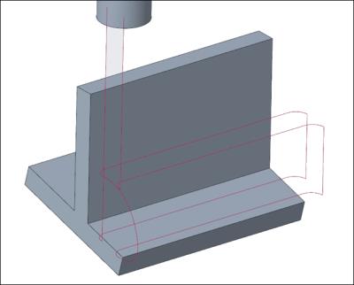
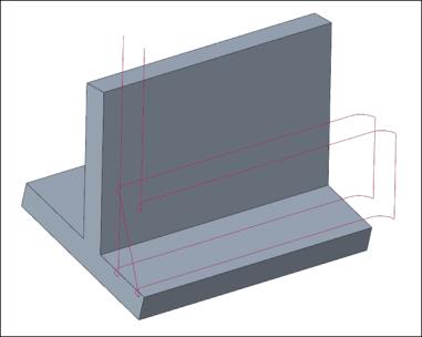
Define the parts and surfaces to use as limits on the tool motions during machining for a gouge-free toolpath.
• Type—Select one of the following option:
◦ Swarf surfaces—Swarf surfaces defined on the References tab are degouged against the toolpath.
◦ Guide curves—Toolpath may gouge the Swarf surfaces defined on the References tab.
• Additional check surfaces—Select part or surfaces to avoid while machining for gouge-free toolpath.
Alternatively, right-click the graphics window and select Additional Check Surfaces.
• Gouge allowance—Enter the allowance to limit tool gouging.
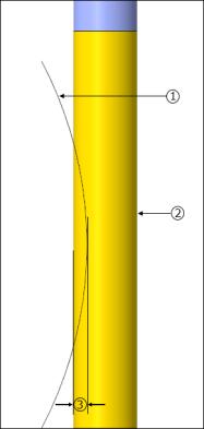
1. Surface
2. Cutting tool
3. Gouge allowance
Options Tab
Open a part or assembly to use as a cutting tool adapter. Alternatively, click  to copy cutting tool adapter from another step.
to copy cutting tool adapter from another step.Tool Motions Tab
To create a Goto Point tool motion, select Goto Point. For more information, see To Create a Goto Point Tool Motion.
To insert a CL command along the toolpath, select CL Command. For more information, see To Insert a CL Command for Tool Motions.
The Tool Motions tab is visible only when you define machining references. |
Process Tab
Use any of the following options for the machining step:
• Calculated Time—Click  to automatically calculate the machining time for the step. The Calculated Time box shows the time.
to automatically calculate the machining time for the step. The Calculated Time box shows the time.• Actual Time—Specify the machining time.
Properties Tab
Specify the name or comments for the step.
• Name—Displays the name of the step. You can type another name.
• Comments—Type the comments associated with the step in the text box or use the following options:
◦  —Read in an existing text file containing step comments and replace any current step comments.
—Read in an existing text file containing step comments and replace any current step comments.◦  —Insert the contents of an existing text file of step comments at the cursor location. Preserve any current step comments
—Insert the contents of an existing text file of step comments at the cursor location. Preserve any current step comments◦  —Save current step comments in a text file.
—Save current step comments in a text file.◦  —Accept the current step comments.
—Accept the current step comments.