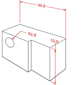
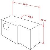
About Aligning Dimensions
Aligning dimensions in a model displays the dimensions in a clean and organized format. You can align dimensions in the X- and Y-direction if the dimensions lie in the same plane as the annotation plane or in a plane that is parallel to the annotation plane and the dimension witness lines are parallel to each other. You can align dimensions in the Z-direction if the dimensions lie in a plane that is parallel to the annotation plane.
Aligning Dimensions in the X- or Y-Direction
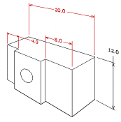
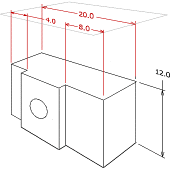
When you align dimensions in the X-, or Y-direction, the dimensions align to a single plane that is perpendicular to the witness lines of all the selected dimensions. The position of the first selected dimension determines the plane to which the dimensions align and the orientation of the witness lines. For example, in the following figure, the first selected dimension with a value of 20.0 determines the plane to which the dimensions align and the orientation of the witness lines.
|
Before Aligning
|
After Aligning (First selected dimension has a value of 20.0)
|
|
|
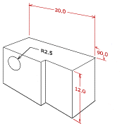
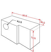
When you align dimensions that include angular dimensions, the first selected dimension establishes the target leader space. Leaders of subsequently selected dimensions align to previous leaders. For example, in the following figure, if you select the dimensions in the order of angular dimension with value 90.0, dimension with value 20.0, and dimension with value 12.0, then the second selected dimension aligns with the first through a parallel witness line (shared in this case). The third selected dimension tries to align to the second dimension and if it cannot align, then it aligns with the first dimension.
|
Before Aligning
|
After Aligning (First selected angular dimension has a value of 90.0. Note that the grey line is shown for explanation purposes only, and is not generated)
|
|
|
Aligning Dimensions in the Z- Direction
When you align dimensions in the Z-direction, Creo Parametric moves the dimensions to the annotation plane of the first selected dimension. Z-direction extension lines are added to the model for dimensions that are moved out of their original placement plane. For example, in the following figure, Creo Parametric moves the dimensions to the annotation plane of the first selected dimension with a value of 20.0.
|
Before Aligning
|
After Aligning (First selected dimension has a value of 20.0. Note that the Z-extension lines are not visible in the solid geometry view. However, it is shown in the figure for clarification only)
|
|
|
