The show modes
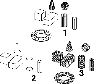
Depending on the show mode you use, your part appears differently. Each mode offers a different view quality. Both shaded and wire mode produce a faceted display, while the edged mode produces a sketch view.
Wire, edged, or color shaded mode

You can set the show mode of a viewport to any mixture of the following options:
The default display mode of Creo Elements/Direct Modeling uses a combination of shaded mode and edged mode. Hidden lines are not displayed.
Color shaded mode
In color shaded mode, which is the default, the part is displayed with a smooth shading effect. Because of the smooth shading you cannot see the facets used for representing the part. Creo Elements/Direct Modeling uses the shading values at the vertices of the facets and interpolates these values; this results in the gradual shading across the facets.
The displayed color is defined by the color of the parts (and/or faces) and the color of the light sources.
Only in the shaded mode can you see the effects of different lights and different light colors. Shaded mode is more realistic than wired or edged views.
Wired mode
In wired mode, the edges of all facets used to represent the part are displayed. The major advantage of using the wired mode is that the facets are clearly visible, which can be important if you want to modify part settings. On some hardware configurations, the display performance of wired mode is also faster than shaded mode.
Edged mode
In pure edged mode, only the edges of a part are displayed, no silhouettes. But edged views of some parts are so simplified that they do not look like the intended part at all. Cylinders and cones appear as two circles. A sphere or a torus does not appear at all because both have no edges. In edged mode, views are generally regenerated more quickly than in shaded or wire mode.
In the default setting the edged mode is combined with the color shaded mode. The color shaded mode gives the best visualization, the edged mode supports the picking of edges and highlights the active part with green edges.
Mixed mode
The mixed mode refers to the show mode settings you can define for individual parts. If they are active, the mixed mode overrides all other settings in the Show menu.
With more than one part displayed and the mixed mode active, you can display each part in a different show mode. You could use the mixed mode, for example, to display copies of the same part in different show modes and take advantage of the varied visualization.