1. Click Annotation and then, in the Annotate group, click the arrow next to  Symbol.
Symbol.Symbol.Create Symbol.• Eligible reference elements (geometrical entities, dimension text, tolerances, dimension lines, dimension reference lines, and points) to position the symbol are highlighted when you hover over them. • After positioning a surface symbol, you can change its reference element by selecting the symbol and clicking  Change Reference on the CMT. Change Reference on the CMT.• Surface symbols are grouped with reference elements; if you move the reference element, the symbol is also moved. However, if you make major changes to the reference element, or if the reference element is an angular dimension, you must reattach the symbol using Change Reference. |
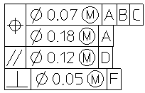
Multiline | Create a multiple-tier tolerance symbol. | ||
Tolerance | Select the type of tolerance symbol. | ||
Composite | Create up to four lines of tolerance information (see below). Composite symbols span two or more lines of text in height. | ||
Value | Click the Value box, the symbol pallet or widget opens. Type the tolerance value. | ||
Datums | Type or select the Primary, Secondary, and Tertiary datums. To specify multiple datum references, click Primary, Secondary or Tertiary. The symbol pallet or widget opens. Type the datum reference characters. | ||
Indicators | Select one of the available indicators, Intersection Plane, Direction Feature, Collection Plane and Orientation Plane.
| ||
Fix text | Click Fix Text. The Fix Text dialog box opens. You can add a prefix, postfix, subfix, and superfix to the symbol. Special characters can be added to fix text. You can also store text in tables for future use. • Click Prefix, Postfix, Superfix, or Subfix to open a text editor. Click Spec Chars to use special characters. Specify the value and click  . Alternatively, type the text in the boxes or select from the list. . Alternatively, type the text in the boxes or select from the list.• Use the buttons above Superfix and below Subfix to align and add a text box to the superfix and subfix, respectively. • Click Put All to add the current fix text to the all fix texts symbols table. • Click Get All to retrieve predefined fix text from the all fix texts symbols table.
|
 and
and  to switch the composite tiers. Following is an example of a composite symbol.
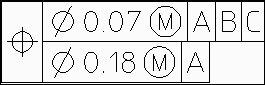
 and to switch tiers. Click Delete to remove a tier.
.PNG)
Symbol Location | If the symbol is snapped to dimension text that is not parallel to the dimension line, select either TOP or RIGHT to place the symbol. The default is TOP and left-aligned. | ||
Form | Select the surface symbol form. | ||
Unit of Proposal | Select the unit of proposal. This determines which sets of predefined parameters appear in some menus below. | ||
Finish Val a1 | Enter the upper roughness value.
| ||
Finish Val a2 | Enter the lower roughness value (Surface (1992)) or middle roughness value (Surface (2002) and Surface (2018)).
| ||
Finish Val a3 | Enter the lower roughness value (Surface (2002) and Surface (2018)). | ||
Add Surface Finish Rows | Select to add an additional two values for the surface finish or roughness in the Surface (2018) version: Finish Val a4 and Finish Val a5. | ||
Process b | Enter the manufacturing process code. | ||
Cov Length c | Enter the covered length.
| ||
Measure f | Enter another roughness measure.
| ||
Allowance e | Enter the machining allowance. | ||
Groove Dir d | Specify the groove direction. | ||
Standard | Specify the surface symbol version: 1992, 2002, or 2018. Depending on the default Standard setting, you can select any one or all the surface symbol versions. See
Set default symbol parameters. If the default Standard setting is All, you can change any symbol to the other version. However, • If the default setting is ISO 1302 - 1992, show only, you can only change a Surface (2002) symbol or Surface (2018) symbol to Surface (1992). • If the default setting is ISO 1302 - 2002, show only, you can only change a Surface (1992) symbol or Surface (2018) symbol to Surface (2002). • If the default setting is ASME Y14.36 - 2018, show only, you can only change a Surface (1992) symbol or Surface (2002) symbol to Surface (2018). |
Shape | Select the type of welding symbol. | ||
Position | Select the orientation of the symbol. | ||
Geo Var | Toggle the menu to display the geometric variable fields g1 to g7. Select the required geometry elements from the cascade lists. The elements comply with the DIN 18800-1 standard. | ||
Text Var | Toggle the menu to display the text variable fields t1 to t7. Enter the required values in the data entry fields.
|
Style: | Select Default (no Style), Datum Target, or Surface.
| ||
Angle: | Specifies the angle between the text base line and the horizontal. If you set the value of the angle to Auto, Creo Elements/Direct Annotation will use the angle of the selected element to set the angle of the symbol. The Get Angle button will change to Flip Symbol so you can position the symbol on the other side of the element.
| ||
Size: | Whether the size of the symbol is relative | ||
Ratio: | The ratio of character width to height. | ||
Slant: | The deviation from vertical of the characters in the text; values must be between -80 and +80 degrees (approximately ±1.39 rad or ±88.88 grad). |
 to complete the operation.
Type of placement | Example |
|---|---|
Symbol location is TOP | 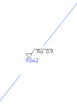 |
Symbol location is RIGHT | 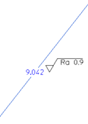 |
Symbol is snapped to geometry | 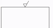 |
Symbol is snapped to geometric tolerance • Single tolerance • Stacked tolerances • Tolerance with fix text | 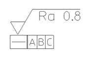 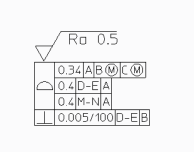 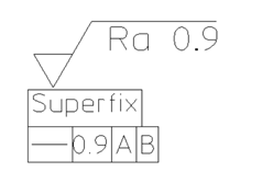 |
Symbol is snapped to dimension text • Dimension text for a horizontal dimension line • Dimension text for a vertical dimension line • Dimension text with fix text | 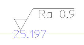 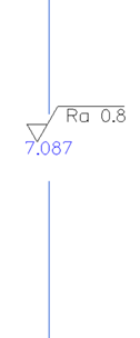 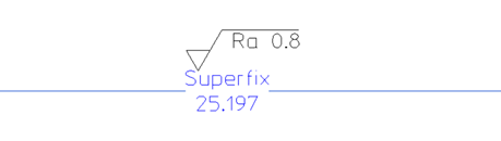 |
Symbol is snapped to dimension line • Linear horizontal dimension line • Linear vertical dimension line • Circular dimension line • Angular dimension line | 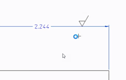 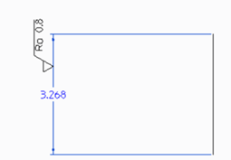 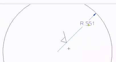 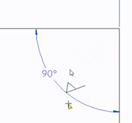 |