One of the final steps before the actual manufacturing starts is providing a 2D drawing. This 2D drawing shows the design as a flattened sheet, the way the original sheet looks before it is bent.
Creo Elements/Direct Sheet Metal can only unfold parts that have a material attached. You must have also specified a manufacturing shop. And, in case the design contains sharp bends, you must have specified a default radius for those bends in your sha_customize file.
The flat generated is based on the bend allowances of the shop. The parameters and the resulting flat may change if a different shop is selected.
Unfolding and reliefless bends
The flat-generation algorithm has been extended to handle no relief cases. The areas where no reliefs are used will be connected in the flat. This behavior is similar to the replacement macro that removes the existing relief. The functionality has been implemented in the main algorithm and therefore does not need any extra handling. It also works on a workplane.
Sheet metal parts created with CoCreate Sheet Metal version 7.5 or earlier do not contain extra information used by later versions when unfolding a part. This information is used by Creo Elements/Direct Sheet Metal to retrieve original analytic curves for bend areas (including punched bends) in a 2D unfold; without this data the curves may unfold to 2D splines. Therefore, parts created with versions of Creo Elements/Direct Sheet Metal prior to 8.0 may not unfold to 2D as expected.
Flats can be produced directly in the Creo Elements/Direct Annotation module of Creo Elements/Direct Modeling. Dep View > Create Flat in the Creo Elements/Direct Annotation Setup group generates a flattened view of the sheet metal part, which can then be annotated using Annotation's wide-ranging, associative 2D drawing tools.
You can also write a flat to a workplane, to an MI file, or to Creo Elements/Direct Drafting.
If you write the output to a workplane, Creo Elements/Direct Sheet Metal positions a new workplane containing the flat parallel to the face you clicked as base face. This flat contains only the unfolded geometry and the bend lines. This allows a limited visual check of the flat for overlaps or other problems. It does not show any attached attributes, marked error areas, and no annotation texts. To see any additional information, you must create the flat in Creo Elements/Direct Annotation, or write it either to an MI file or directly to Creo Elements/Direct Drafting.
If Creo Elements/Direct Drafting is running, you can write the output to Creo Elements/Direct Drafting and the drawing will appear there.
Optionally you can define the position of the flat in the Creo Elements/Direct Drafting or workplane coordinate system.
Unfolding sheet metal parts with non-orthogonal side faces
When designing sheet metals parts that are to be flush with other parts of your construction, you may want to "taper" the edges as shown in the following figure. Such non-orthogonal side faces result in different (non-congruent) face geometry on either "side" of the flat.
In the shop, non-orthogonal side faces are usually produced in one of two ways:
• By adding material to the sheet metal part. An additive process such as welding can be used for this purpose. In this case, the shorter flat length applies.
• By removing material from the sheet metal part. A subtractive process such as grinding or flame cutting can be used for this purpose. In this case, the longer flat length applies.
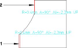
The following figure shows such a sheet metal part with non-orthogonal side faces (1 and 2) designed to be attached to another part.
If both the "inside" and the "outside" faces are accounted for, the flat of such a sheet metal part looks as follows:
Proceed as follows to account for non-orthogonal side faces when unfolding:
1. Click Sheet Metal and then, in the Post Process group, click Unfold 2D. The Unfold dialog box opens.
2. Click the base face. (Unless you select Both Sides in the following step, your choice of base face governs the flat size.)
3. If you want the flat to account for both sides, select Both Sides.
4. Click Blind Feats to project blind features to the flat.
The face of the blind feature must be connected to either the top face or the bottom face of the sheet metal part.
Unfolding non-planar surfaces
Creo Elements/Direct Sheet Metal allows you to unfold the following non-planar surface types:
• Cylindrical surfaces
• Conical surfaces
• Linear swept B-spline surfaces
Unfolding side faces
Creo Elements/Direct Sheet Metal allows you to correctly unfold side faces that have features like chamfers. You can also control tool handling to display geometrical details of inner tools in the flat. For details, see
Controlling the information output to the flat.
 Dep View >
  Create Flat in the Creo Elements/Direct Annotation Setup group generates a flattened view of the sheet metal part, which can then be annotated using Annotation's wide-ranging, associative 2D drawing tools.
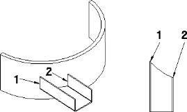
 Unfold 2D