This tutorial provides a number of guided exercises that provide you with hands-on experience in the use of Creo Elements/Direct Modeling IDF Data Adapter (PCB I/F). Sample Board Station and IDF files for these exercises are supplied with Creo Elements/Direct Modeling IDF Data Adapter (PCB I/F).
To complete an IDF based example, you need to select the IDF interface format. To complete an EIF based example, you need to select the EIF interface format. See
Getting Started for instructions.
The following examples provide instructions for both the IDF based tutorial and the EIF based tutorial. Decide which tutorial format you want to use. Do not mix both formats.
• You are familiar with solid modeling and know Creo Elements/Direct Modeling.
• You are familiar with Mentor Graphics Board Station and/or the IDF exchange format.
Setting Up the Tutorial
The Creo Elements/Direct Modeling IDF Data Adapter (PCB I/F) installation directory includes the tutorial subdirectories for the EIF and IDF based examples provided in this chapter. Before you can begin the tutorial you must set up the tutorial directories for EIF and/or for IDF based examples.
You can perform one or both of the following steps:
Proceed as follows if you want to go through the IDF based examples:
1. Copy the tutorial subdirectories for the IDF based examples from <installdir>\personality\sdpcb\idftutorial to a new directory of your choice (such as C:\tmp\pcbtutorial).
2. Start Creo Elements/Direct Modeling.
3. Enter the following command in the Creo Elements/Direct Modeling user input line to change to the directory containing the IDF tutorial data:
cd "c:/tmp/pcbtutorial"
This directory contains a sample sdpcb_customize file that sets the IDF library format and the associated library paths.
4. Start Creo Elements/Direct Modeling IDF Data Adapter (PCB I/F).
Setting Up the EIF Based Examples
Proceed as follows if you want to go through the EIF based examples:
1. Copy the tutorial subdirectories for the EIF based examples from <installdir>\personality\sdpcb\eiftutorial to a new directory of your choice (such as C:\tmp\pcbtutorial).
2. Start Creo Elements/Direct Modeling.
3. Enter the following command in the Creo Elements/Direct Modeling user input line to change to the directory containing the EIF tutorial data:
cd "c:/tmp/pcbtutorial"
This directory contains a sample sdpcb_customize file that sets the EIF library format and the associated library paths.
4. Start Creo Elements/Direct Modeling IDF Data Adapter (PCB I/F).
Example 1: Creating a New Part Model in Creo Elements/Direct Modeling IDF Data Adapter (PCB I/F)
This exercise teaches you how to create a completely new part model without making use of any imported PCB assembly part. The new model represents a simple resistor. You will use construction lines to define the geometry of this new model. You will then store the new model in a separate subdirectory. You can perform this exercise in either EIF or IDF format.
Proceed as follows:
1. In Creo Elements/Direct Modeling, make sure that the length unit is set to mm.
2. Create a default workplane. For a new PCB assembly, the default workplane is at the global origin.
3. In Creo Elements/Direct Modeling, create an infinite horizontal constructions lines at 0 on the current workplane.
4. In Creo Elements/Direct Modeling, create infinite vertical construction lines at 0 and 21 on the same workplane.
5. In Creo Elements/Direct Modeling IDF Data Adapter (PCB I/F), click PCB and then, in the Assembly group, click New. The Create PCA dialog box opens.
6. Type test-pca in the Name box and / in the Owner box.
7. Click to create an empty PCB assembly for the new part.
8. Click PCB and then, in the Model group, click Macro.
9. Click Cylinder. The Cylinder dialog box opens.
10. Specify the following data in the Cylinder dialog box:
ModelName
r_55
PartType
resistor
11. To specify the position of pin 1, select point 0,0 on the current workplane.
12. To specify the position of pin 2, select point 21,0 on the current workplane.
13. Specify the following data in the other fields of the Cylinder dialog box:
BodyDiam
3.2
BodyLength
15
LeadDiam
0.3
MountClear
4
14. Click to generate the new model.
15. Examine the resulting model of a resistor. Note that the part origin (in this example: the location of pin 1) is located at the world origin. This is imperative for the accurate placement of models used as substitutes for imported PCB assembly parts.
16. Optionally, store the newly created model in a library subdirectory for resistor models:
a. Use the standard operating system commands to create a subdirectory named resistors in a directory of your choice (such as c:\tmp\my_library).
b. Click PCB and then, in the Filing group, click Library.
c. Click Add. The Add Library dialog box opens along with the Libraries table.
d. In the Add Library dialog box, click Name and enter a name such as specials as the library name.
e. Click Directory and enter the applicable pathname (such as c:\tmp\my_library).
f. Click .
g. Click PCB and then, in the Model group, click Filing.
h. Click Store One. The Store Model dialog box opens along with Local Lib table (browser).
i. In the Local Lib browser, select r_55 in the Name column and click Apply.
j. In the Libraries browser, select specials in the Name column and click Apply.
k. In the Store Model dialog box type c:\tmp\my_library\resistors as the SubPath.
l. In the Store Model dialog box, click to save the newly created resistor model in a library named specials in the resistors subdirectory of your tutorial fileset.
The Add command in the Library list is intended for the addition of libraries in your current session only. If you want to use a given library permanently, be sure to specify that library in your sdpcb_customize file. For details see
Configuring Creo Elements/Direct Modeling IDF Data Adapter (PCB I/F).
Example 2: Creating a New Part Model from an Imported Board Station Geometry File
This example assumes that Creo Elements/Direct Modeling IDF Data Adapter (PCB I/F) is set to the EIF interface format. For details see
Getting Started.
In this example you will import the 2D geometry of a resistor from Board Station data provided in C:\tmp\pcbtutorial\data. You will use the workplane set of this part to create a 3D model of this resistor.
Please note that the res_typ8 model you are about to create is the same as the res_typ8 model provided in your C:\tmp\pcbtutorial\model directory.
Proceed as follows:
1. Translate the Board Station file to Creo Elements/Direct Modeling IDF Data Adapter (PCB I/F) EIF format.
a. Click PCB and then, in the Filing group, click ECAD Adapter.
b. Click Translate. The Translate dialog box opens along with the File Browser.
c. Click MGGeomFile in the Translate dialog box to specify or to select the Board Station geometry file res_typ8.bsasc from the C:\tmp\pcbtutorial\data subdirectory.
d. Click OK.
The Board Station file has now been translated to the Creo Elements/Direct Modeling IDF Data Adapter (PCB I/F) EIF file res_typ8.bsasc.eif.
2. Import the newly created EIF file.
a. Click PCB and then, in the Filing group, click ECAD Adapter.
b. Click Import. The Import dialog box opens.
c. Click EIF-File to specify the file res_typ8.bsasc.eif. file from the File Browser.
d. Click .
e. If necessary, use the Drawlist to display this part.
The part, a "surrounding box" or "block" representation of a resistor, is displayed. It is based on the component height and component outline data extracted from the Board Station source file.
3. Turn on the workplane set res_typ8_wps in the Drawlist.
4. Change the view of the imported part such that you can see the 2D outline of the resistor. You are now going to use this workplane set to create your 3D standard part.
5. Click PCB and then, in the Model group, click Macro.
6. Click Cylinder. The Cylinder dialog box opens.
7. In the Cylinder menu, specify the following:
ModelName
res_typ8
Parttyp
select resistor from the browser
Pin 1 Pos
catch All WPs, pick left construction point (triangle)
Pin n Pos
catch All WPs, pick right construction point (triangle)
BodyDiam
3.81 (measure width)
BodyLength
10.16 (measure distance between the two vertical white lines)
LeadDiam
0.5
MountClear
1
8. Click .
You have just created a 3D resistor by means of the Cylinder macro functionality of Creo Elements/Direct Modeling IDF Data Adapter (PCB I/F). The dimensions of this cylinder model are based on the exact dimensions imported from the Board Station source file.
* Save the newly created 3D Model in a Creo Elements/Direct Modeling IDF Data Adapter (PCB I/F) library.
1. Click PCB and then, in the Model group, click Filing.
2. Click Store One. The Store Model dialog box opens along with Local Lib table (browser).
3. Specify the model name: res_typ8
4. Click LibPath and select the applicable library path for the 3D resistor model. For example:
c:\tmp\ee_parts
5. Click .
6. If you have created sublibraries, click SubPath and select the applicable sublibrary for the 3D resistor model. For example:
c:\tmp\ee_parts\resistors
7. Click .
8. Clear the viewport; click PCB and then, in the Utilities group, click (Delete All 3D).
The newly created 3D resistor model is now available for selection from the library in which you saved it. You can use this model in other examples presented in this tutorial.
Example 3: Creating a PCB Assembly
This example can be done in either EIF or IDF format. In this example you will create a new PCB assembly in Creo Elements/Direct Modeling IDF Data Adapter (PCB I/F). You will begin by creating an assembly structure. Then you will add the appropriate profiles plus associated 3D models.
1. Create the Creo Elements/Direct Modeling IDF Data Adapter (PCB I/F) assembly structure.
a. Click PCB and then, in the Assembly group, click Create. The Create PCA dialog box opens.
b. Type board1 in the Name box and / in the Owner box.
c. Click .
d. Display the Structure Browser to view the structure of your newly created PCB assembly.
2. Add a profile.
a. Click PCB and then, in the Profile group, click Add. The Add Profile dialog box opens along with the Profile Select Table.
b. Click To Assy and select the PCB assembly. The active PCB assembly is selected by default.
c. In the Add Profile dialog box, click Profile to display the Profile Select Table.
d. Select the appropriate profile from the Profile Select Table. (The Height box appears under the Parameters section.):
▪ For EIF: select pcb-outline
▪ For IDF: select Board-Outline
e. Enter 1.6 for Height.
If you wanted to add another workplane immediately after this one, you would click Next and repeat steps 3 to 5 above. In this example, you add the workplanes one at a time without using the Next option.
f. Click .
g. View the Structure Browser to see the resulting structure.
3. In the Creo Elements/Direct Modeling main menu, click File > Open. The Load file browser opens. Select sheet_metal.pkg from C:\tmp\pcbtutorial\data and click Load. The sheet metal part contained in this package is shown in Figure 20.
Figure 147. Figure 20. Sheet Metal Part
4. Position the workplane set on the sheet metal part.
a. Click PCB and then, in the Assembly group, click More.
b. Click Move by WP. The Move by Profile dialog box opens.
c. Click the appropriate workplane:
▪ For EIF: pcb-outline
▪ For IDF: Board-Outline
d. Click Profile, and specify the following:
Origin:
Select Center in Catch and select the red face. Selecting the red face gives the correct offset distance of the WP-set from the sheet metal part.
Normal:
Select Face Normal and click on the red face.
The option Face Color should be on in Show. The option Project should be off in Catch.
e. Click to move the workplane.
5. Create the new PCB outline. To do this, you need to add the required workplanes to the set and draw the profile.
a. Click Applications and then, in the Base group, click Modeling to switch to the Modeling application.
b. Click Modeling and then, in the Draw group, click the arrow next to Project. Click Face in the Project Geometry section to project the sheet metal face to the appropriate workplane:
▪ For EIF: pcb-outline
▪ For IDF: Board-Outline
c. Delete all circles from the projected geometry. For visual clarity, you may want to remove sheet_metal from the drawlist.
d. Switch to PCB application (click Applications and then, in the Free group, click PCB) and use Add Profile (click PCB and then, in the Profile group, click Add) to add another profile to your new board1 assembly:
▪ For EIF: drill-unplated
▪ For IDF: Drilled-Holes-Mtg
Use the same procedure as for the first profile you added in the current example.
e. Add sheet_metal to the drawlist.
f. Project the sheet metal face to the newly added workplane.
g. Delete all geometry except circles from the drill-unplated or Drill-Holes-Mtg profile. Again, you may want to remove sheet_metal and pcb-outline (for EIF) or Board-Outline (for IDF) from the drawlist.
h. Change all circle radii of the drill-unplated orDrilled-Holes-Pin profile to 1.5. Switch to Modeling application and then use Change Radius (click Modeling and then, in the Modify 2D group, click Radius.
i. Add another profile (refer step d) to your board1 assembly:
▪ For EIF: all-route-keepout
▪ For IDF: Route-Keepout-All Use the same procedure as for the previous profile.
j. Project the sheet metal face to the newly added workplane.
k. Delete all geometry except circles from the all-route-keepout or Route-Keepout-All profile.
l. Change all circle radii of the all-route-keepout or Route-Keepout-All profile to 5.
If you need more restrict areas, you can add other profile types in the same way as above.
You have just designed a new PCB outline using a number of different profiles. Now you will use the Update command (switch to PCB application; and click PCB and then, in the Assembly group, click Update. The Update PCA dialog box opens along with Local Lib table ) to create the PCB assembly from these profiles.
6. Update the PCB assembly.
a. Click PCB and then, in the Assembly group, click Update. The Update PCA dialog box opens along with Local Lib table. Note that board1 is selected automatically.
b. Click ProfSet to display the Punch Profile Table.
c. In the Punch Profile Table, click the Board radio button.
d. Set the drill-unplated (for EIF) or Drill-Holes-Mtg (for IDF) active for board punch operations:
a. Identify the table row that includes the drill-unplated or Drill-Holes-Mtg profile.
b. In the same table row, double-click on the dash (-) character in the Board column. This activates the associated punch profile, telling Creo Elements/Direct Modeling IDF Data Adapter (PCB I/F) which profiles to use in any board-related punch operation.
c. In the Punch with Profiles of section of the Update PCA dialog box, click the Board select button.
d. Click to update the PCB assembly.
7. Optionally, you can now save the entire assembly tree of your new PCB assembly as a package for further use.
a. Click PCB and then, in the Filing group, click Tree.
b. Click Store. The Save Tree dialog box opens along with the File Browser.
c. In the File Browser, select the suffix .pcbpkg.
d. In the File Browser, select the appropriate data directory, C:\tmp\pcbtutorial\data.
e. In Filename box, of the File Browser, type board1 as the PCA file name.
f. Click OK in the File Browser.
g. In the Save Tree dialog box, click .
Example 4: Adding Parts to a PCB Assembly
This example can be done in either EIF or IDF format.
In this example you will pre-place electronic parts which are influenced by the mechanical environment, and you will see how mechanical design data can be combined with a solid model of a PCB to create an assembly that contains both mechanical and electronic parts.
The electronic parts used in this example are connectors stored in preconfigured libraries of 3D models for use with EIF and IDF based PCB assemblies.
At the end you will have a completed PCB assembly as shown in Figure 21.
Figure 21. Completed Assembly Structure
1. Unless the board1 assembly is already loaded, load it now.
a. Click PCB and then, in the Filing group, click Tree.
b. Click Load. The Load Tree dialog box opens along with the File Browser.
c. Select board1.pcbpkg from the File Browser.
d. Click OK.
2. Add a 3D model of an EE part to the assembly structure.
a. Click PCB and then, in the Model group, click Filing.
b. Click Load. The Load Model dialog box opens along with the Libraries table (browser).
c. From the Libraries browser, click C:/Temp/eiftutorial or C:/Temp/idftutorial and select model.
d. Select the conn_3pin_audio.MIBS model file.
e. Click .
This model is loaded at the PCB assembly origin. Use the Structure Browser to check that this model is included in the LIB_PART assembly. The newly loaded model is not yet part of your new board1 assembly.
3. Add a 3D model to the board1 assembly structure.
a. Click PCB and then, in the Part group, click Add. The AddPart dialog box opens along with the Local Lib table (browser).
b. Click Model and select conn_3pin_audio from the Local Lib table.
c. Click PCA and select the default selection board1.
d. Enter a1 as the reference designator for the 3D part in the Refdes box. Note that an instance (named a1) of this 3D part is now located at the origin of your PCB assembly.
Be sure to specify a unique reference designator for each part you add to your PCB assembly.
e. Click .
4. Position a1 on the PCB Assembly.
a. Click PCB and then, in the Part group, click Move. The Move Part dialog box opens.
b. In Move Part dialog box, click Part and then select a1.
c. Click the Rotate button (immediately below the Part button).
d. Enter a Rotation angle of 180 degree.
e. Click . The part will be rotated about its local Z axis.
5. Position a1 on the sheet metal part. Check Figure 21 for guidance.
a. In the Move Part dialog box, click Part and select a1.
b. Click Translate.
c. Click Two Points.
d. You are prompted for a "from" point. Click Catch and select the circle of the front face of a1.
e. You are prompted for a "to" point. Click Catch and select the circle of the front face of board1.
6. Load two more 3D Parts from the applicable Creo Elements/Direct Modeling IDF Data Adapter (PCB I/F) library.
Load bnc.MIBS and eurodin_96pin.MIBS. Use the same method you used to load conn_3pin_audio to the assembly structure.
7. Add two instances of bnc.MIBS and a single instance of eurodin_96pin.MIBS to the board1 assembly structure. Again, use the AddPart command. The reference designators for these instances are specified in the table below.
Table 2. Reference Designators
Source
Reference Designator
bnc.MIBS
a2
bnc.MIBS
a3
eurodin_96pin.MIBS
a4
8. Position a2.
a. Position a2 in the sheet metal hole with the green face. Use Catch Center just as you did for a1.
9. Position a3.
a. Position a3 in the sheet metal hole with the yellow face. Use Catch Center just as you did for a1.
Figure 149. Figure 22. Part a4
10. Position a4. As you have projected the outline of board1 from the sheet metal part, there is now a board1 face (board1 is the green printed circuit board) which is identical in size and shape to the purple face and is above the sheet metal part. Position a4 on the board1 face.
11. Update the board1 assembly.
a. Click PCB and then, in the Assembly group, click Update. The Update PCA dialog box opens.
b. In the Update PCA dialog box, click the Board, Model, and Part check boxes in the Punch with Profiles of section.
c. Click ProfSet to display the Punch Profile Table.
d. Make sure that all applicable profiles are set to active for Board, Model, and Part.
e. In the Update PCA dialog box, click to punch the holes.
f. Check that the required punch operations were performed.
12. For EIF, export the board1 assembly so that you can use it with Board Station.
Since the assembly is a newly created assembly that was not imported from Board Station, only a .brd file will be created when you export it; however, no comps file is created.
a. Click PCB and then, in the Filing group, click ECAD Adapter.
b. Click Export. The Export IDF dialog box opens.
c. In the PCA box, board1 is selected by default.
d. In the Export IDF dialog box, click Export File. Specify board1.eif as the file name.
e. Use the File Browser to save the board1.eif file in the data subdirectory of your EIF tutorial directory.
f. Click OK.
The new .brd file can now be transferred and used with Board Station software.
13. For IDF, export the board1 assembly to an IDF format file.
a. Click PCB and then, in the Filing group, click ECAD Adapter.
b. Click Export. The Export IDF dialog box opens.
c. In the PCA box, board1 is selected by default.
d. Specify board1.idf as the export file name.
e. Use the File Browser to save the board1.idf file in the data subdirectory of your IDF tutorial directory.
f. Click OK.
Example 5: Modifying a Board Station PCB Design
This example assumes that Creo Elements/Direct Modeling IDF Data Adapter (PCB I/F) is set to the EIF interface format. For details see
Getting Started. In this example you will import, modify and export a Board Station design.
You will learn how to import an existing PCB assembly and how Creo Elements/Direct Modeling IDF Data Adapter (PCB I/F) "remembers" which files to update and where they are located when you perform the Export command.
1. Make sure that there are no parts/assemblies in Creo Elements/Direct Modeling. If there are, save your work and click PCB and then, in the Utilities group, click (Delete All 3D) to clear the viewports.
2. Translate the Board Station design.
a. Click PCB and then, in the Filing group, click ECAD Adapter.
b. Click Translate. The Translate dialog box opens along with the File Browser.
c. Click MGGeomFile in the Translate dialog box to select the Board Station geoms file board1.bsasc from the data subdirectory of the EIF tutorial directory.
d. Click MGCompFile to select the Board Station comps file comps.comps_1.
e. Click .
Normally you would have to copy the board1.bsasc and comps.comps_1 files from your Board Station design directory.
3. Import the EIF file and create the part models from the Board Station data.
a. Click PCB and then, in the Filing group, click ECAD Adapter.
b. Click Import. The Import dialog box opens along with the File Browser.
c. Use the File Browser to select the board1.bsasc.eif file from the C:\tmp\eiftutorial\data directory.
d. Make sure that the LibPath check box is cleared, as you want to create the part models from the Board Station data.
e. Click .
The box-shaped part models you see on your screen have been created from Board Station data.
4. Clear the viewport. Click PCB and then, in the Utilities group, click (Delete All 3D).
5. Import the EIF file again and use the predefined part models from the Creo Elements/Direct Modeling IDF Data Adapter (PCB I/F) supplied libraries to create "real" 3D part models from the Board Station data.
a. Click PCB and then, in the Filing group, click ECAD Adapter.
b. Click Import. The Import dialog box opens along with the File Browser.
c. Click EIF-File to select the eif file board1.bsasc.eif from the data subdirectory of your EIF tutorial directory.
d. Click LibPath and make sure that the model subdirectory of your EIF tutorial directory is set to active.
e. Click .
6. Modify the board shape.
a. Clear the Drawlist.
b. Add the pcb-outline workplane located in the PROF subdirectory in the board1 directory to the drawlist.
c. Set this workplane to be the Active Workplane.
d. Make this workplane editable:
▪ Click PCB and then, in the Profile group, click Edit. The Edit Profile dialog box opens.
▪ In the Edit Profile dialog box, click Profile and then click the workplane you want to make editable. Make sure that the Edit radio button is clicked.
e. Replace the 2 rounded corners by square corners.
7. Update the PCB assembly.
a. Add board1 to the Drawlist.
b. Click PCB and then, in the Assembly group, click Update. The Update PCA dialog box opens.
c. In the Update PCA dialog box, click the Board, Model and Part check boxes in the Punch with Profiles of section.
d. Click ProfSet to display the Punch Profile Table.
e. Make sure that all applicable profiles are set to active for Board, Model, and Part.
f. In the Update PCA dialog box, click to punch the holes.
g. Check that the required punch operations were performed.
8. Export the PCB Assembly.
a. Click PCB and then, in the Filing group, click ECAD Adapter.
b. Click Export. The Export dialog box opens.
c. Overwrite the existing file board1.bsasc.eif.
9. Click . Creo Elements/Direct Modeling IDF Data Adapter (PCB I/F) remembers from where you imported the PCB assembly and creates two new files in the same directory:
◦ board1.brd and
◦ comps.comps_new
which you would normally transfer back to Board Station for use with the Librarian and Layout.
You can use the files provided in the IDF tutorial directory to repeat this example in the IDF world. The only difference is that you do not need to translate any file prior to import.
Example 6: Modifying an Existing PCB Design in IDF Format
This example assumes that Creo Elements/Direct Modeling IDF Data Adapter (PCB I/F) is set to the IDF interface format. For details see
Getting Started.
This example is similar to
Example 5: Modifying a Board Station PCB Design. However, in this example you will import an existing PCB design in IDF format. Following mechanical modification in Creo Elements/Direct Modeling IDF Data Adapter (PCB I/F), you will export this design back to an IDF format file.
1. Make sure that there are no parts/assemblies in Creo Elements/Direct Modeling. If there are, save your work and click PCB and then, in the Utilities group, click (Delete All 3D) to clear all viewports.
2. Select and activate the library containing the 3D mechanical models you want to apply:
a. Click PCB and then, in the Filing group, click Library.
b. Click Set. The Set Library dialog box opens along with the Libraries table.
c. Unless you have already done so in one of the earlier examples, add the library named model contained in the C:\tmp\idftutorial to your current library selection.
3. Import the IDF file and create the part models from the Board Station data.
a. Click PCB and then, in the Filing group, click ECAD Adapter.
b. Click Import. The Import IDF dialog box opens.
c. Click Board Name and use the File Browser to select the board1.int file from the C:tmp\idftutorial\data.
d. Click Part File and use the File Browser to select the board1.pro file from the C:tmp\idftutorial\data.
e. Make sure that the LibPath check box is cleared, as you want to create the part models from IDF data.
f. Click .
The box-shaped part models you see on your screen have been created from IDF data.
4. Clear the viewport. Click (Delete All 3D).
5. Import the IDF files again and use the predefined part models from the Creo Elements/Direct Modeling IDF Data Adapter (PCB I/F) supplied libraries to create "real" 3D part models from the IDF data.
a. Click PCB and then, in the Filing group, click ECAD Adapter.
b. Click Import. The Import IDF dialog box opens.
c. Click Board Name and use the File Browser to select the board1.int file from the C:tmp\idftutorial\data.
d. Click Part File and use the File Browser to select the board1.pro file from the C:tmp\idftutorial\data.
e. Click LibPath.
f. Click .
6. Modify the board shape.
a. Clear the Drawlist.
b. Add the Board-Outline workplane located in the PROF subdirectory in the board1 directory to the drawlist.
c. Set this workplane to be the Active Workplane.
d. Make this workplane editable:
▪ Click PCB and then, in the Profile group, click Edit. The Edit Profile dialog box opens.
▪ In the Edit Profile dialog box, click Profile and then select the workplane you want to make editable. Make sure that the Edit radio button is clicked.
e. Replace the 2 rounded corners by square corners.
7. Update the PCB assembly.
a. Add board1 to the Drawlist.
b. Click PCB and then, in the Assembly group, click Update. The Update PCA dialog box opens.
c. In the Update PCA dialog box, click the Board, Model, and Part check boxes in the Punch with Profiles of section.
d. Click ProfSet to display the Punch Profile Table.
e. Make sure that all applicable profiles are set to active for Board, Model, and Part.
f. In the Update PCA dialog box, click to punch the holes.
g. Check that the required punch operations were performed.
8. Export the PCB Assembly.
a. Click PCB and then, in the Filing group, click ECAD Adapter.
b. Click Export. The Export IDF dialog box opens along with File Browser.
 New. The Create PCA dialog box opens.
 to create an empty PCB assembly for the new part.
 ECAD Adapter.
 (Delete All 3D).
 Modeling to switch to the Modeling application.
 Project. Click
  Face in the Project Geometry section to project the sheet metal face to the appropriate workplane:
 PCB) and use Add Profile (click PCB and then, in the Profile group, click Add) to add another profile to your new board1 assembly:
 Radius.
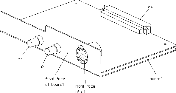
 Filing.
 Add. The AddPart dialog box opens along with the Local Lib table (browser).
 Move. The Move Part dialog box opens.
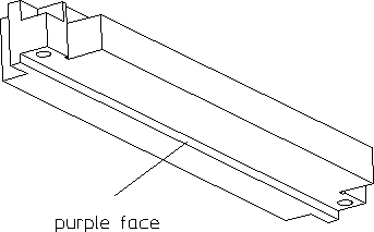
 Import. The Import IDF dialog box opens.