Creo Elements/Direct Sheet Metal provides a number of functions which can be used to provide the technology database with additional manufacturing related information (such as shop-specific tool IDs) for each shop. When you unfold a sheet metal part, this additional information can be passed with the flat for use in postprocessing applications such as NC systems.
In the Technology Database (TDB), you can use the :FLAT-TEXT keyword to specify additional annotation text to be included in the flat drawing. This "flat text" will be appended to the bend line in the 2D flat.
In general, the :FLAT-TEXT keyword consists of a list of :COLUMN entries that the :FLAT-TEXT entry belongs to. Each entry may be preceded by a unit qualifier (:MM, :DEG). The default units are the units in that table. For each entry, you can optionally specify the number of decimal places of the output value. For example, an entry such as
returns the angle (e.g.: 33.5) of the air bending process with one decimal place.
The defined values may be incorporated into a leading text string in which the values are referred to as {#} entries. The following example shows the "Hems" table of the sha_demoshop.lsp file.
The :FLAT_TEXT statement near the bottom of this table implies the following:
• The hem related string to be attached to the hem bend line in the flat specifies the hem distance in mm.
• In this hem related string, the hem distance is followed by the tool direction.
When you unfold a sheet metal part that includes a hem, the associated flat text string is derived from the :FLAT-TEXT keyword shown above. An example of such a flat text string in a drawing file is provided below.
FLAT-INFO
In the Technology Database (TDB), you can use the :FLAT-INFO keyword to specify additional tool-related information or other data relevant to the flat.
The :FLAT-INFO keyword uses the same syntax as the :FLAT-TEXT keyword (see
FLAT-TEXT). The :FLAT-INFO defaults to the FLAT-TEXT. Note that the :FLAT-INFO statement can be placed anywhere in a shop file table.
The following example shows a customized version of the "Clover Leaf" table in a shop file.
The :FLAT_INFO statement (near the bottom of this table) implies the following:
• A string specifying the punch tool number and a description of the tool will be added to the flat of the sheet metal part containing clover leaf punch features.
The value of the Punch_no string is the TOOL_ID specified in the "Clover Leaf" table.
• The value of the Description string is taken from the :DESCR column of the "Clover Leaf" table.
When you unfold a sheet metal part that includes a clover leaf punch feature, the associated flat info string is derived from the :FLAT-INFO keyword shown above and will be attached as info text to the corresponding flat geometry. An example of such a flat info string in a drawing file is provided below.
SHA_TOOL_INFO: Punch_no= 16708 Description= 6695
Automatic Feature Replacement in Flats
As of Creo Elements/Direct Sheet Metal rev. 6.0, special mechanisms are provided to enable the user to selectively remove or replace features from the flat of a sheet metal part. For example, bend reliefs and corner reliefs can be replaced by special manufacturing-driven geometries such as round corner reliefs or even "no reliefs" for thin sheet metals.
The associated control settings can be defined in the sha-define-default-settings section of each shop file. See:
Enabling or Disabling the Feature Replacement Functionality
To enable the feature replacement functionality for a given shop, set the following toggle in the sha-define-default-settings section of the associated shop file.
To disable the feature replacement functionality for a given shop, set the following toggle in the sha-define-default-settings section of the associated shop file.
Enabling or Disabling the Replacement Functionality by Process
The automatic replacement of Creo Elements/Direct Sheet Metal controlled features can be selectively enabled or disabled by process. The macros provided for this purpose are listed below. Note that each macro name identifies the process (such as "hem") for which it is intended.
For examples, to enable the automatic replacement of stamp features in flats, you need to specify the following in the sha-define-default-settings section of the shop file:
CoCreate Modeling rev. 6.0 is supplied with replacement macros for reliefs and corner reliefs only. Other process replacements are planned for future releases or are available through customer-driven consultancy services.
Specifying Replacement Features
You can specify a :REPLACEMENT-INFO statement for each feature you want to remove or replace by a different feature.
• The :REPLACEMENT-INFO statement must be added to the associated tool table.
• The :REPLACEMENT-INFO statement uses a syntax similar to
FLAT-TEXT. You can specify one of the predefined macro names provided for feature replacement.
For example, if you want to replace round corner reliefs in your flats by the corner reliefs defined through the sha_rnd_crn_relief_repl macro, you must add the following statement to the "Round Corner Relief" table:
If you want to replace a specific feature in your flat, be sure to enable the feature replacement for the associated process. See
If you want to completely remove a rectangular corner relief, you must add the following statement to the "Square Corner Relief" table:
:REPLACEMENT-INFO ("sha_remove_corner_relief")
If you want to remove a normal rectangular relief, you must add the following statement to the "Rectangular Relief" table:
:REPLACEMENT-INFO ("sha_remove_relief {1}" :VERT)
Unfolding Side Faces
Creo Elements/Direct Sheet Metal allows you to correctly unfold side faces that have features like chamfers. You can also control tool handling to display additional geometrical details of inner tools in the flat. The macros that are provided for this purpose in the sha_demoshop.lsp file are listed below.
Examples of how you can use the above macros are given below.
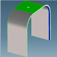
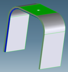
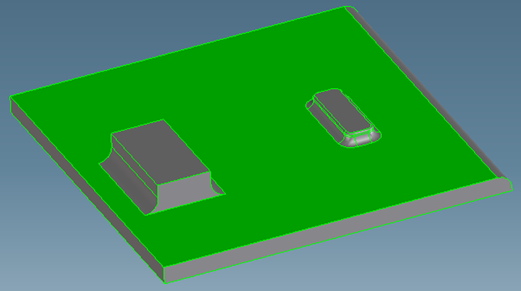
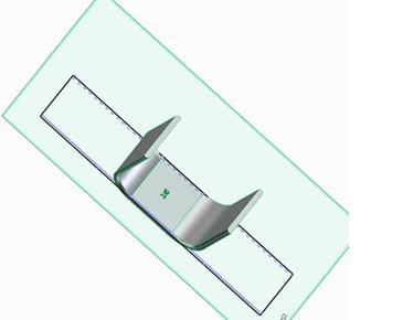
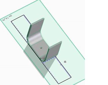
• sha_set_flat_sheet_border_handling and sha_set_flat_tool_handling allow you to control side-face handling for sheet borders and tools, respectively. For example, in the following source part, the base face is highlighted in green and circumferential welding edges are visible as chamfers on both sides.
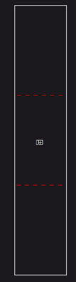
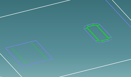
For the above source part, if you only activate sha_set_flat_sheet_border_handling using (sha_set_flat_sheet_border_handling t), only the outer edges are projected, resulting in the following flat:
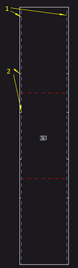
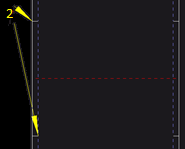
• The remaining border-handling macros allow you to control the additional geometrical details. You can activate sha_set_flat_sheet_border_show_inner_contour, sha_set_flat_sheet_border_show_detail_contour, sha_set_flat_sheet_border_inner_contour_color, and sha_set_flat_sheet_border_detail_contour_color as shown in the following example:
2. Detail contour which is created by unfolding the chamfer.
• For tools in planar faces, you can independently display hidden lines and silhouette lines.
◦ If hidden lines are turned off, the lines are not shown as hidden (dashed) lines but as solid lines.
◦ If silhouette lines are turned off, they are not shown at all.
For example, in the following source part, the base face contains features.
If you activate sha_set_flat_tool_handling, sha_set_flat_planar_tools_calculate_hidden_lines, and sha_set_flat_planar_tools_calculate_silhouette, the feature contours are projected as shown below:
• sha_set_flat_feature_standard_colors allows you to suppress standard colors for Creo Elements/Direct Sheet Metal features. Standard colors are the default. To suppress the standard colors, set sha_set_flat_feature_standard_colors to nil.
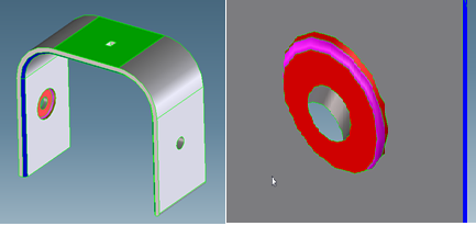
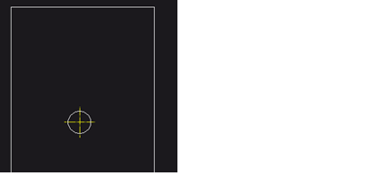
• sha_set_flat_feature_detail allows you to project the details of invisible tools which are not Creo Elements/Direct Sheet Metal features. An example of such a feature is shown below.
You can further control visibility of the edges of such features in the flat by setting sha_set_flat_tool_show_boundary and sha_set_flat_tool_show_detail as shown below.
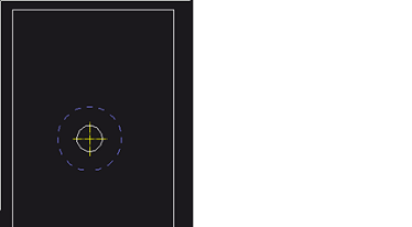
(sha_set_flat_tool_show_detail nil) and (sha_set_flat_tool_show_boundary nil)
(sha_set_flat_tool_show_detail nil) and (sha_set_flat_tool_show_boundary t)
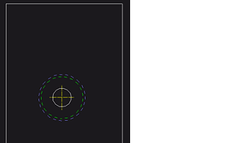
(sha_set_flat_tool_show_detail t) and (sha_set_flat_tool_show_boundary t)
• sha_set_flat_hide_inner_bottom_edges allows you to convert inner edges on the bottom side to hidden edges as shown below.
Base face is the top face
Base face is the bottom face
The conversion is correct for standard chamfers along sheet metal sides, but may not be correct in complex cases.
Limitations:
• Creo Elements/Direct Sheet Metal removes bend area lines inside tools that have Creo Elements/Direct Sheet Metal features.
• You cannot unfold side faces which are linear swept B-splines surfaces.
• For tools in bend regions or along the sheet boundary, Creo Elements/Direct Sheet Metal does not show hidden or silhouette lines.
• For tools in bend regions, Creo Elements/Direct Sheet Metal does not support invisible bend area lines.
• If a Creo Elements/Direct Sheet Metal feature does not exist:
◦ Creo Elements/Direct Sheet Metal may not fully recognize the tool.
◦ Geometrical elements on opposite faces may not be recognized.
◦ For tools in bend regions, invisible bend area lines are not suppressed. Creo Elements/Direct Sheet Metal considers all geometrical elements as relevant if a tool is inside a bend.