You can modify a pattern of screw connections. To learn how to create a pattern, see
Add a screw connection.
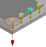
When you modify a linear pattern, one of the connections must remain in its original position. The red arrow in the image above indicates the fixed connection point. You can change the fixed connection point by changing FixConn or FixPart.
The cyan arrow shows you the direction of the linear pattern.
To change a pattern of screw connections,
1. Click Part Library and then, in the Screw conn group, click the arrow next to Modify.
2. Select one of the following of pattern you want to change from Hole pattern section:
◦ Linear
◦ Radial
◦ Grid
◦ Scribed Circle
3. Select the Pattern in the Structure Browser.
4. The fixed position is indicated by a red arrow in the viewport. If you want to change this,
◦ Click FixConn. and select a hole feature in the viewport or Structure Browser.
◦ Click FixPart and select a screw in the viewport. The connecting hole is automatically detected. If this doesn't work, try FixConn. instead.
5. The current values are displayed for reference. Change the values in the New values section.
◦ Where you see a + or -, you can change the number of connections before (+) or after (-) the connection defined as the fixed position.
◦ When you modify a linear grid, direction 1 is indicated by the green arrow and direction 2 is indicated by the cyan arrow in the viewport.
 Modify.
 Linear
 Radial
 Grid
Grid Scribed Circle
 to complete the operation.