Mold parts can be split into their core, cavity, silhouette and undercut faces. You can let Mold Design create the core, cavity, undercut, and slider features automatically, or define them manually yourself, or a combination of both methods. A check utility allows you to check which faces do not yet belong to a mold part feature.
You can let Mold Design attempt to create automatically core, cavity, undercut, and slider features on your part. The features can later be modified or deleted altogether.
To split a part automatically with respect to the pull direction,
1. Click Mold Design and then, in the Part Splitting group, click the arrow next to Splitting.
2. Click Automatic The Autom. Part Splitting dialog box opens with the active part selected.
3. If necessary, click Part and specify a different part to split.
4. Specify the Pull Direction in which the part will be split. Use the Direction 3D tool.
5. Select amongst the following options to determine what is done with silhouette faces:
◦ Split Silh Surface splits silhouette faces and assigns their different parts to the core or cavity feature, as appropriate. This option is only available when the Extend Feat option (see below) is set to optimize Core/Cavity or All features, and splitting is only done when such a split is optimal within the context of the part.
◦ Detect Boss/Pocket detects a connected set of silhouette faces that have neighboring faces belonging to only one type of feature (for example, the silhouette faces of a boss or pocket on a core feature), and adds those faces to that feature. Detection is done automatically during the Extend Feat optimization (see below); it can therefore only be switched off when this option is set to None (that is, no optimization).
◦ Extend Feat optimizes the creation of the Core/Cavity feature, the Undercut feature, All features or None of them, by adding silhouette faces appropriately.
◦ Cleanup Silh assigns all remaining silhouette faces to the Core feature or to the Cavity feature, or leaves them as they are (None).
◦ Keep Critical Silh imprints critical silhouette edges on undercut faces onto the part; otherwise they are discarded.
You can change at any time how faces have been assigned to features after automatic part splitting.
6. Two options further control how features are handled:
◦ Detect Slider checks connected undercut faces and tries to find a direction for which a slider can be created, and creates the slider feature if so. (Note that a slider feature can only be created where there is only one, unambiguous solution for it.)
◦ Split Core/Cavity Feat splits non-connected sets of faces of the core and cavity into multiple features.
7. Click Preview to preview the part splitting, or click OKto complete the operation.
The Preview mode does not highlight automatically-created slider features. These features are only created after you click OK.
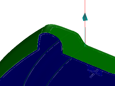
The following two graphics illustrate the Extend Feat function The first graphic shows the mold part without optimization; two silhouette faces remain. The second graphic uses Core/Cavity optimization and the silhouette faces are assigned to the core feature.
Mold Design provides a tool to split a part by collecting its individual faces to belong to the core, cavity or slider. Such classifications can be modified. It is also possible to have the Advisor "predict" a classification using the automatic part splitting method, and then to modify this classification later.
To split a part manually,
1. Click Mold Design and then, in the Part Splitting group, click the arrow next to Splitting.
2. Click Manual. The Manual Part Splitting dialog box opens with the active part selected.
3. If necessary, click Part and specify a different part to split.
4. Select from the Type cascade list the form type for which faces and features should be added: Core, Cavity, or Slider.
5. If you select Slider, specify with the Direction 3D tool the pull direction for the slider.
6. Enter a name in the Feat Name field for the new feature to which the collected faces are to be added, or specify an existing feature to modify. In particular, you can modify features created with the automatic part splitting mode.
7. You can now add faces to the new or existing feature as follows:
◦ Click Feature and specify a feature whose faces are to be added. You can select a feature from the Mold Feature table, from the Structure Browser, or click one in the viewport.
◦ Click Faces (under Add Faces by), and use the Select tool to select faces to be added.
◦ Click Boundary to select all faces enclosed by a boundary defined by a collection of other faces or edges. To select the edges or faces of the boundary, use SHIFT-left-mouse-button to select the edges or faces, and SHIFT-middle-mouse-button to complete the list. To use the PartingLine option:
1. Click PartingLine to define the boundary by edges from parting line features.
2. Click somewhere in the interior of the boundary to indicate the "Side" of it enclosing the feature.
3. Adjust the selections as necessary and click Accept.
The graphic below is an example of using the Boundary option: First the boundary faces are selected, then a face is clicked in the interior of the boundary, causing the selected faces to be assigned to a cavity feature:
8. To remove faces from the feature, click Faces (under Remove Faces by), and use the Select tool to select faces to be removed.
9. You can temporarily highlight the features on the part by clicking one of the feature types on under Highlight Feature.
10. Click Next to complete the current feature and keep the menu open to create a new feature of the same type, or click OKto complete the operation.
You can check a mold part to determine if all faces belong to a core, cavity or slider feature. Those faces that do not belong to such a feature are highlighted.
To check a part's splitting,
1. Click Mold Design and then, in the Part Splitting group, click the arrow next to Check Split. The Check Part Splitting dialog box opens.
2. If necessary, click Part and specify a different part to check.
3. To hide undercuts during the check, click Remove Undercut Feature on.
4. Click Check it to highlight the faces not belonging to a core, cavity, or slider feature.
5. Click OK when you are finished.
Parting lines
To create a parting line, click Mold Design and then, in the Part Splitting group, click Parting Line. The Parting Line dialog box opens.
A parting line feature consists of a list of edges and a direction specified for those edges. It is not possible to store more than one direction in a parting line feature. This means that all edges of a parting line feature must have the same (unique) direction. Parting line features are also exclusive: an edge can only belong to a single parting line feature. Parting Line feature can be used in the following commands:
• Pull Direction specification (set Default pull direction and in all commands using direction specification)
• Manual Part Splitting
• Parting Surface Creation
For parting line features the following commands are available:
• Manually create and modify parting line features using the Parting Line dialog.
• Create parting line features automatically using the Keep as Parting Line toggle in the Imprint Open Profile dialog box.
• Check the parting line feature to see whether edges define open or closed loops.
• Use the Parting Line dialog to display all parting line features of the owning part: arrows indicate the pull direction for all edges specified as parting line features.
• Display parting line features and their direction in the custom feature report.
 Splitting.
 to complete the operation.
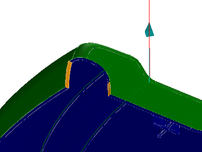
 Check Split. The Check Part Splitting dialog box opens.
 Parting Line. The Parting Line dialog box opens.