|
|
All LBCs use the same icon -- compare 3 and 5.
|
|
|
All LBCs use the same icon -- compare 3 and 5.
|
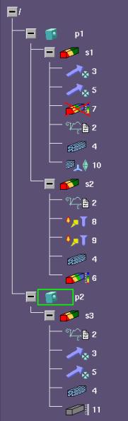
Structure Browser Abbreviation | Icon Type | Description |
|---|---|---|
acc | 3 & 5 | Acceleration name |
edhfl | 3 & 5 | Edge heatflow name |
edf | 3 & 5 | Edge force name |
edhfl | 8 & 9 | Edge heatflow name |
fafreeconv | 8 & 9 | Face free convection name |
fahfl | 8 & 9 | Face heatflow name |
fcf | 3 & 5 | Face force name |
fcp | 3 & 5 | Face pressure name |
fixtemp | 8 & 9 | Fixed temperature name |
gcnd | 10 | Concentrated mesh condition name |
grv | 3 & 5 | Gravity name |
hgen | 8 & 9 | Heat generation name |
hpt | 10 | Hardpoint name |
mat | 2 | Material assigned |
mate3 | 3 & 5 | Parts mated together name |
mesh | 4 | Mesh name |
meshcnd | 10 | Mesh conditions |
result | 6 | Result name (valid and available) |
result | 11 | Result that is retrievable |
result | 7 | Result that is invalid |
spin | 3 & 5 | Spin name |
study | s1 & s2 | Study name (complete study) |
study | -- | Incomplete study (gray) |
temp | 8 & 9 | Part temperature name (complete study) |
tr_constr | 3 & 5 | Translational constraint name (vertex, edge, face) |
tr_fdispl | 3 & 5 | Translational force displacement name |
vxf | 3 & 5 | Vertex force name |
vxhfl | 8 & 9 | Vertex heatflow name |