When you analyze an assembly, you must create relations between the mated faces. The relation defines faces which are mated, so you must make sure your parts are lined up before you create the relation.
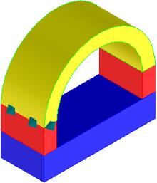
Mate relations are indicated in the viewport by a 3D octahedron symbol, shown in the image below between the yellow and red parts on the left side:
To create a mate relation for analysis,
1. Click FEA and then, in the Mechanical LBC group, Mate Reltn.
2. Click Study and select an analysis study in the Structure Browser.
3. Type a Name for the relation.
4. Select a Mate Mode:
◦ Manual: Use this mode if you want to select the reference and related faces yourself.
◦ Semiautomatic: Use this mode to display a list of valid possible relations. You may select either the reference or related face to constrain the list to relations that are valid for a single face. Select a line or lines in the list to create the relation.
◦ Automatic: Automatically detects all valid relations.
5. Click Ref Face and select a reference face in the viewport. The reference is one of the faces included in the relation.
6. Click Related Face and select a related face in the viewport.
7. Click Next to define another relation.
8. Click to complete the operation.
To change the color of the mate relation symbols, click Modify and then, in the Settings group, click the arrow next to Mechanical Symbols. Click Constraints. The Constraints dialog box opens. Change the Sym Color in the dialog box.
 to complete the operation.