You can use the Spline Channel Editor to create virtual guides in the following ways:
• Create a guide along a pipe.
• Create a guide through a hole.
• Create a guide on a face.
• Create a guide between two points.
• Create a guide on a line.
To create a guide along a pipe or a cylindrical face,
1. On the Guides tab, in the box adjacent to , type or select a diameter for the guide.
2. Click Along pipe and Create.
3. In the L box, type or select the length of the guide.
4. Select a point on a cylindrical surface. The guide is created at this point.
5. If required, rotate the guide around the pipe using the “+1”, “-1”, “+10”. or “-10” buttons. Use the “-” buttons for clockwise rotation and the “+” buttons for counterclockwise rotation. The numbers denote the minimum and maximum rotation steps.
6. If required, modify the diameter of the guide using the “+” and “-” buttons.
The following image shows how you can create and rotate a guide along a pipe.
To create a guide through a hole in a part,
1. On the Guides tab, in the box adjacent to , type or select a diameter for the guide.
2. Click Thru hole and Create.
3. In the L box, type or select the length of the guide.
4. Select the radial surface of a hole. The guide is created along the axis.
5. If required, modify the diameter of the guide using the “+” and “-” buttons.
The following image shows how you can create a guide through a hole.
To create a guide on a face,
1. On the Guides tab, in the box adjacent to , type or select a diameter for the guide.
2. Click On face and Create.
3. In the L box, type or select the length of the guide.
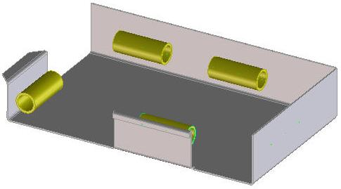
4. Select a point on a face. The guide is created at this point.
5. If required, rotate the guide.
a. To align the guide parallel to a 2D or 3D edge, click and select the edge.
b. To incrementally rotate the guide by an angle, specify the angle of rotation in the box adjacent to and click .
6. If required, modify the length of the guide using the “+” and “-” buttons that are adjacent to the angle value.
7. If required, modify the diameter of the guide using the “+” and “-” buttons that are adjacent to the diameter value.
The following image shows how you can create a guide on a face.
To create a guide between two points,
1. On the Guides tab, in the box adjacent to , type or select a diameter for the guide.
2. Click 2 Pnts and Create.
3. Specify a start point and an end point. The guide is created between the two points. Use the 3D CoPilot for further positioning and click when done.
4. If required, modify the diameter of the guide using the “+” and “-” buttons.
To create a guide on a 2D line,
1. On the Guides tab, in the box adjacent to , type or select a diameter for the guide.
2. Click on 2D Line and Create.
3. Select a 2D line on a workplane. The guide is created along the line.
4. If required, modify the diameter of the guide using the “+” and “-” buttons.
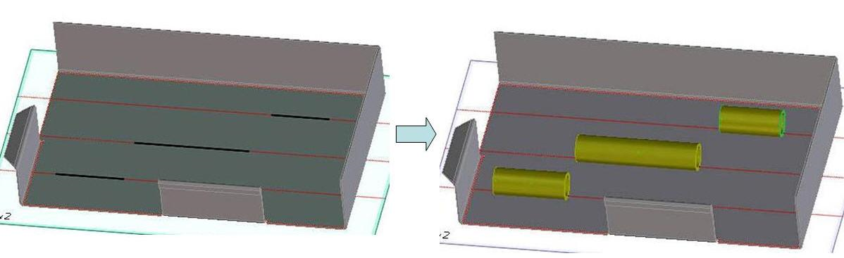
The following image shows how you can create a guide on a 2D line.
 , type or select a diameter for the guide.
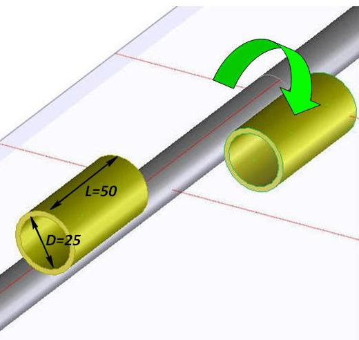
 , type or select a diameter for the guide.
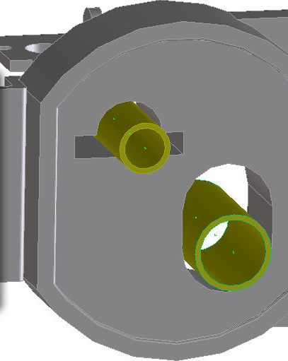
 , type or select a diameter for the guide.
 and select the edge.
 and click
  .
.
 , type or select a diameter for the guide.
 when done.
 , type or select a diameter for the guide.