Dialog Field (Keyword) | Type | Label | Description |
|---|---|---|---|
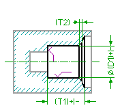
Drill Dia (DRILL_DIA) | Toleranced Length | D1 | Specifies the diameter of the hole to be drilled. If you have added a tolerance to this parameter through the Creo Elements/Direct Annotation 3D module or by direct specification within the dialog box, it is written into the output file to be transferred to the receiving CAM system (in either ISO or values). See the Description about specifying the Tolerance of a length value for further information. |
DrillDepth (DRILL_DEPTH) | Toleranced Length | T1 | Specifies the drilling depth. The depth is defined as the length of the drilled cylinder and does not include the tip of the drill tool. If you have added a tolerance to this parameter through the Creo Elements/Direct Annotation 3D module or by direct specification within the dialog box, it is written into the output file to be transferred to the receiving CAM system (in either ISO or values). See the Description about specifying the Tolerance of a length value for further information.See also
Blind Hole Step Parameters. |
Cham Depth (CHAMFER_DEPTH) | Length | T2 | The depth of the chamfer measured in direction of the axis. |
Cham.Angle (CHAMFER_ANGLE) | Angle | The tool tip angle of the sink tool. | |
BttmQuality (BOTTOM_SF_QUAL) | Specifies the surface quality of the plannar bottom of the drilled hole. See the Description about specifying the Surface Quality for further information. | ||
Side Quality (SIDE_SF_QUAL) | Specifies the surface quality of the side of the drilled hole. See the Description about specifying the Surface Quality for further information. |
Dialog Field (Keyword) | Description |
|---|---|
Show/Hide Image (IMAGE_SHOWN) | Shows or hides the graphical representation of the machined hole. |
Show/Hide Tolerance & Quality (TOLERANCE_AND_QUALITY) | Shows or hides additional tolerance-related input fields. |