Dialog Field (Keyword) | Type | Label | Description |
|---|---|---|---|
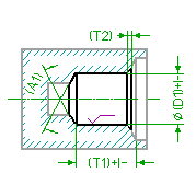
Drill Dia (DRILL_DIA) | Toleranced Length | D1 | Specifies the diameter of the hole to be drilled. If you have added a tolerance to this parameter through the Creo Elements/Direct Annotation 3D module or by direct specification within the dialog box, it is written into the output file to be transferred to the receiving CAM system (in either ISO or values). See the Description about specifying the Tolerance of a length value for further information. |
DrillDepth (DRILL_DEPTH) | Toleranced Length | T1 | Specifies the drilling depth. The depth is defined as the length of the drilled cylinder and does not include the tip of the drill tool. If you have added a tolerance to this parameter through the Creo Elements/Direct Annotation 3D module or by direct specification within the dialog box, it is written into the output file to be transferred to the receiving CAM system (in either ISO or values). See the Description about specifying the Tolerance of a length value for further information. |
Cham Depth (CHAMFER_DEPTH) | Length | T2 | The depth of the chamfer measured in direction of the axis. |
Cham.Angle (CHAMFER_ANGLE) | Angle | The tool tip angle of the sink tool. | |
Cone Angle (CONE_ANGLE) | Angle | A1 | The tip angle of the drill tool to be used for the drilling operation. A 118 degrees default is used. The following restrictions apply: 0 < A1 <= 180 degrees, that is, you can create a flat blind hole, but there are special commands to do so (simply replace the BLINDHOLE by FLAT_BLINDHOLE in the name of the command). |
MeasMode (MEAS_MODE) | There are two different methods to specify the depth of a step: Rel: The relative method, the depth is measured from the end of the previous step. Abs: The absolute method, the depth is measured from the start point. If a relative depth is specified and the user changes the depth of a previous step the other steps will move. If an absolute depth is specified, the steps are adjusted if a previous step is changed. | ||
Side Quality (SIDE_SF_QUAL) | Specifies the surface quality of the side of the drilled hole. See the Description about specifying the Surface Quality for further information. |
Dialog Field (Keyword) | Description |
|---|---|
Show/Hide Image (IMAGE_SHOWN) | Shows or hides the graphical representation of the machined hole. |
Show/Hide Tolerance & Quality (TOLERANCE_AND_QUALITY) | Shows or hides additional tolerance-related input fields. |