Use the wire editor to modify vertices and/or wire body edges.
You must license and activate the Parametrics module to use this command.
To modify a wire feature with the Wire Editor,
1. Activate the Parametrics module:
a. Click File > Modules. The Modules dialog box opens.
b. On the Modules pane, click Parametrics.
2. Click 3D Geometry and then, in the 3D Curve group, click Wire Editor. The Wire Editor dialog box opens.
3. Vertex/Edge: Select one or more vertices or edges. Depending on whether you make a single or multiple selection, and on the type of selected curve (line, circle, b-spline, etc.) Creo Elements/Direct Modeling displays the different possible modify operations:
◦ Position:
Position selected elements. If the selected elements lie in a plane, Creo Elements/Direct Modeling displays an additional workplane for direction selection. Creo Elements/Direct Modeling creates an adjustable, temporary relation set to find the proper solution. Select a positioning method:
▪ Free: Move selected elements using the Position dialog.
▪ Planar: Move the plane's geometry using the position dialog. Selected elements remain coincident with the temporary workplane.
◦ Chg Rad:
Change the radius of a 3D circle or arc. Creo Elements/Direct Modeling creates an adjustable, temporary relation set to find the proper solution (see step 6). Select a method:
▪ Chg Fillet: Change the fillet radius.
▪ Keep Vertex: Change the radius of a circle or arc while keeping its vertices fixed.
▪ Keep Center: Change the radius of a circle or arc while keeping its center fixed.
▪ Keep Peak: Change the radius of a circle or arc while keeping its midpoint fixed.
▪ Keep Vert+Tng: Change the radius of the circle or arc while keeping its tangent and either its start vertex or its end vertex fixed.
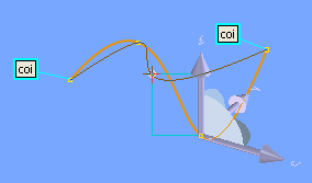
◦ Mod As Spline:
Change a 3D spline curve. Creo Elements/Direct Modeling creates an adjustable, temporary relation set to find the proper solution.
◦ Split Ed: Split the selected wire edge.
◦ Delete Ed: Delete selected wire edges.
◦ Convert Ed:
Convert selected wire edges to spline curves.
• Creo Elements/Direct Modeling tries to automatically fix edges so that wires are only modified locally. When such a relation set has no solution after several dragging attempts, Creo Elements/Direct Modeling asks you whether these automatically fixed edges should be unfixed. After you've modified the relation set, Creo Elements/Direct Modeling turns off automatic unfixing.
• The more edges your surface has, the more relations required for mesh modification. Creo Elements/Direct Modeling better solves relations sets of smaller mesh size. Reasonable feedback is also more likely when editing smaller meshes.
• The default relations set created after you select an element selection is a good first choice for modifying the selected elements. Even for mesh changes that appear simple, the relation set may have no solution or only solutions in a certain (e.g., move) direction. If you receive no feedback after making your selection, the relation set is likely too restrictive. You should modify it by adding or removing relations or by changing the selected elements.
• The Surface Editor supports the
fix point concept for spline curves by a split and join approach: Spline curves with fix points are split at their fix points before the wire modification, such that each spline curve segment can be modified individually. If possible, spline curve splits at fix points are removed after the wire modification.
 Wire Editor. The Wire Editor dialog box opens.