A Fluent user interface is available for Creo Elements/Direct 3D Access. The Fluent user interface facilitates faster access to commands by grouping the commands according to their functions.
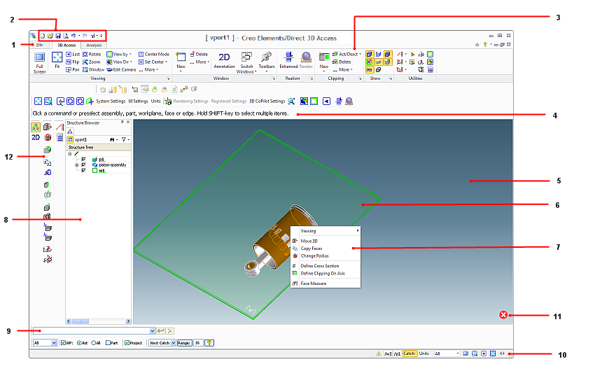
The Creo Elements/Direct 3D Access user interface consists of the following elements:
As Creo Elements/Direct 3D Access allows advanced users to customize their systems, all displays may not look like the above image.
1. File Tab
2. Quick Access Toolbar
3. Ribbon
4. Prompt Bar
5. Viewport
6. Workplane
7. Context Menu
8. Browser Bar
9. User Input Line
10. Status Bar
11. OK and Cancel buttons
12. Modeling Commands toolbar
When the mouse cursor is over a current viewport, you can middle-click to perform the following operations:
• Middle-click to end a command.
• Middle-click and rotate to zoom.
• Middle-click and drag to rotate.
• Middle-click, press SHIFT, and drag to pan.
You can also right-click the current viewport and drag to pan. To change the mouse interaction mode, click File > Settings > Viewport and click the CoCreate 17.0 mouse interaction mode check box in the Dynamic Viewing pane of the Viewport Settings dialog box.
File Tab
The File button in the upper-left corner of the Creo Elements/Direct 3D Access window opens the File menu. The File menu contains the following commands:
• New Session: Resets the system to its start-up state.
• Open: Opens a file browser. You can select a file type to load.
• Open From Database: Opens a file browser. You can select a file type to load from the database which is connected to the current Creo Elements/Direct 3D Access session. For example, if you activate Model Manager, Database changes to Model Manager. If no database is active, this command is not available.
• Save: Opens a file browser. You can select a file type to save.
• Save To Database: Opens a file browser. You can select a file type to save to the database which is connected to the current Creo Elements/Direct 3D Access session. For example, if you activate Model Manager, Database changes to Model Manager. If no database is active, this command is not available.
• Database: Offers commands that are specific to the database which is connected to the current Creo Elements/Direct 3D Access session. The name of this command changes according to the database. For example, if you activate Model Manager, Database changes to Model Manager. If no database is activated, this command is not available.
• Print: Prints a model or an assembly.
• Render to File: Renders the contents of the current viewport to a file. This option is only enabled if the module “Rendering” is active.
• Modules: Opens a Modules dialog box and allows you to start or stop one of the following:
◦ Modules (Rendering, Inspection, and others)
◦ Data Interfaces (Creo Parametric, UGS SolidEdge, and others)
• Settings: Changes the Creo Elements/Direct 3D Access and system settings.
• Toolbox: The Toolbox menu is an empty menu that you can use to place your frequently-used commands.
• Options: Opens the Options dialog box, in which you can customize the Quick Access Toolbar.
• Exit: Closes Creo Elements/Direct 3D Access. Before exiting, you are asked for confirmation.
• Search for Command: Type the name of the command and then select the relevant command from the list to start the command. For example, type delete in the Search for Command box and then select a relevant Delete command from the list.
Quick Access Toolbar
The Quick Access toolbar is by default at the top of the Creo Elements/Direct 3D Access window. It provides quick access to frequently-used commands. You can customize the Quick Access toolbar by adding, removing and reordering commands (buttons).
Ribbon
The ribbon contains commands organized as a set of tabs. On each tab, related commands are grouped. The following figure shows the different elements of a ribbon.
1. Tab
2. Group
3. Button
4. More button
5. Dialog Box Launcher
1. Tab: The available tabs are 3D Access tab and Analysis tab.
2. Group: Commands are placed within groups according to their function.
3. Button: Each button on the ribbon represents a command and consists of an icon and, in most cases, a label. Some buttons have an icon and an arrow. The frequently-used buttons are large while other buttons are small in size. The ribbon has the following types of buttons:
◦ or (Large or small button with an icon and a label): Click this button to start an operation. For example, click Delete to delete a clipping feature.
◦ or (Large or small button with an icon and an arrow not separated by a line): An arrow indicates the existence of a list. Click this button to open a list of related commands. When no line separates a button, the icon and arrow perform same action.
◦ or (Large or small button with an icon and an arrow separated by a line): A line, or separation, between the icon and arrow indicates that the icon and arrow perform different actions. Click the icon on this button to start an operation. Click the arrow to open a list of related commands. The icon of the last-selected command in the current session is displayed on the button.
• For some commands, a dialog box opens.
• The label remains unchanged irrespective of the last selection.
• The tooltip shows the name and a description of the command that the icon represents.
• The procedural topics assume that the icon of the default command is displayed on a button though you may see the icon of your last-selected command.
4. More: The rarely-used commands are listed at the end of most groups under the More button to optimize the user interface.
5. Dialog Box Launcher: Opens the settings dialog box related to the commands in the group. For example, click the Dialog box Launcher in the Viewing group to open the Viewport Settings dialog box.
Prompt Bar
The prompt bar is used for general system feedback, messages, or user guidance. The prompt bar is not active by default. If the prompt bar is not open, the prompt text is displayed in the status bar at the lower end of the window. To view the prompt bar:
1. Click 3D Access and then, in the Window group, click Toolbars.
2. Click Prompt Bar.
You can position the prompt bar anywhere on the screen.
Viewport
The viewport covers the main portion of the user interface. It is the graphics area of the user interface where you design your part.
You can have several viewports to view your part simultaneously from different sides and in different modes. You can resize viewports. The viewport is in between the ribbon and the status bar.
Workplane
A workplane is a transparent, infinite plane. Workplanes allow you to work on any section of your part from any perspective. Use the workplane to draw 2D geometry, machine the part, and create sophisticated shapes.
Context Menu
The context menu opens when you select and right-click any element in the viewport in preselection mode. Depending on the current context and the selected object, the commands on the context menu change.
Dialog Box
A dialog box opens when you click buttons on the Ribbon or the Quick Access Toolbar or some items on the context menu. You can select elements or set properties in the dialog box. Complete or cancel the operation with or , respectively.
OK and Cancel
Complete or cancel the operation with the or buttons, respectively. These buttons are only available in the viewport if a dialog box is active. You can click to open a dialog box during an operation. For example, if you are moving faces and recognized features, you can click to open the Move dialog box.
Browser Bar (Structure Browser and other Browsers)
The browser bar shows all opened browsers; for instance the structure browser. The structure browser displays all 3D objects and elements (parts, assemblies, workplanes, and so on) and their interrelationships. You can also use the browser to:
• Specify parts and assemblies for 3D Access operations; for example, to move a part or an assembly within the structure, and
• Select objects and elements (double-click an object or element in the structure browser).
To open the structure browser, press F12, or:
1. Click 3D Access and then, in the Window group, click Toolbars.
2. ClickBrowser Bar.
User Input Line
The user input line is used to enter commands, general expressions, or text. To view the user input line:
1. Click 3D Access and then, in the Window group, click Toolbars.
2. Click User Input Line.
Status Bar
The status bar is at the bottom of the 3D Access window and is always available. The status bar has the following commands:
• Full Screen: Switches the full screen mode on and off (F11).
• Window: Defines a new viewing window.
• Last View: Displays the last view.
• Fit: Fits the content into the viewport.
• Previous Application: Switches to previous application.
• Show Alert History: Shows the alert history.
The status bar also shows the current workplane and part and the current settings for Catch and Units.
If the prompt bar is not open the prompt text is displayed in the left side of the status bar.

 or
or (Large or small button with an icon and a label): Click this button to start an operation. For example, click
  Delete to delete a clipping feature.
 or
or  (Large or small button with an icon and an arrow not separated by a line): An arrow indicates the existence of a list. Click this button to open a list of related commands. When no line separates a button, the icon and arrow perform same action.
 or
or  (Large or small button with an icon and an arrow separated by a line): A line, or separation, between the icon and arrow indicates that the icon and arrow perform different actions. Click the icon on this button to start an operation. Click the arrow to open a list of related commands. The icon of the last-selected command in the current session is displayed on the button.
 Toolbars.
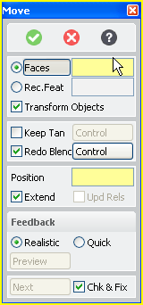
 or
or  , respectively.
 to open a dialog box during an operation. For example, if you are moving faces and recognized features, you can click
  Browser Bar.
 Full Screen: Switches the full screen mode on and off (F11).
 Window: Defines a new viewing window.
 Last View: Displays the last view.
 Fit: Fits the content into the viewport.
 Previous Application: Switches to previous application.
 Show Alert History: Shows the alert history.