
This tutorial is intended to be used alongside Pro/ENGINEER Wildfire 3.0 Tryout Edition.
Please make sure that Pro/ENGINEER Wildfire 3.0 Tryout Edition is installed on your machine before continuing. Files used or created during this tutorial cannot be used with any other version of Pro/ENGINEER other than the Tryout Edition. Your hosting Hands-on Workshop Application Engineer will have this set up for you. If not, please refer to the READ ME FIRST document.
Download the model files here. Save the zip file to your desktop.
Your web browser and Pro/ENGINEER can be resized and laid out as shown below to facilitate your experience.
 Positioning Tutorial Window |
It is recommended that you maximize the amount of working area on your screen by setting your monitor to the highest resolution setting, for example 1600x1200.
Use the Commands at the top of the page to navigate through the tutorial. Click Next to proceed to the next slide and Previous to return to the previous slide. Click Home to return to the beginning of the tutorial. If the page contains more information than the visible screen, a scroll bar will appear along the vertical side. Scroll through the entire contents before progressing to the next step.
You will see various icons throughout the tutorial:
There are several conventions used in this tutorial:
In this tutorial, you will learn the basics of Drawing creation. Both a part and assembly drawing will be created.
Step 1: Create a New Part Drawing 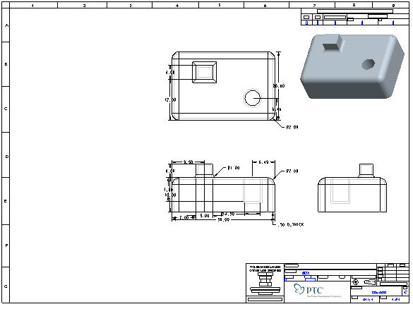
Step 2: Create, move, and manipulate drawing views
Step 3: Create, move and manipulate drawing details such as dimensions and notes.
Step 4: Make design changes in the model and in the drawing.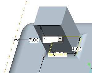
Step 5: Create a New Assembly Drawing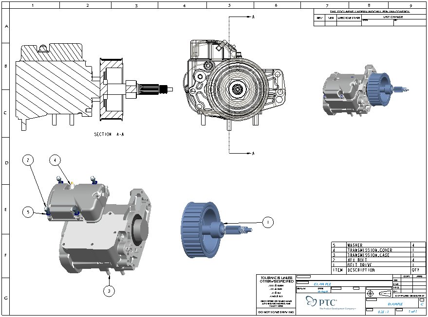
As an alternative to having this open along-side Pro/Engineer, you can also view a printable version by clicking here.
|
Task 1. Create a New Part Drawing |
Start Pro/ENGINEER Wildfire 3.0 if necessary.
If Pro/ENGINEER is already running ensure all windows are closed, and all items from the previous exercise are erased from memory.
In the Navigator Folder Browser ![]() , browse to the following folder C:\HANDS-ON_WF3\DRAWING_TUTORIAL.
, browse to the following folder C:\HANDS-ON_WF3\DRAWING_TUTORIAL.
Right-click the DRAWING_TUTORIAL folder and select Set Working Directory.
Click the New ![]() icon on the main toolbar and select Drawing as the Type in the New Object dialog box.
icon on the main toolbar and select Drawing as the Type in the New Object dialog box.
In the New dialog box, type BOX as the Name.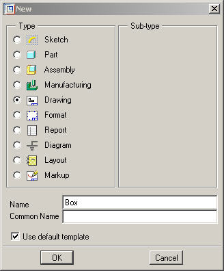
|
|
Note that the Use Default Template option is enabled. |
Click OK from the New dialog box.
Click Browse from the New Drawing dialog box and select BOX.PRT as the Default Model.
Click Open.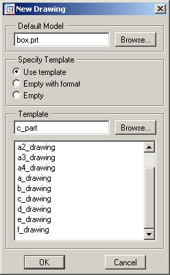
Under Specify Template, select the radio button Use template.
Under the Template section, click Browse and select C_PART.DRW.
Click Open.
|
|
Drawing templates may be referenced when creating a new drawing. They automatically create the views, set the desired view display, create snap lines, and show model dimensions based on the template. |
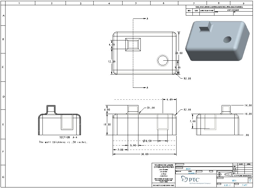
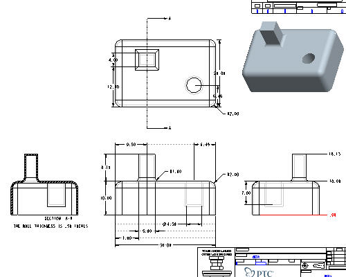
Click OK from the New Drawing dialog box. The template drawing will automatically layout the drawing.
|
|
The use of drawing templates can save an enormous amount of time by automatically laying out your standard view with dimensions, cross-sections, notes, etc. To make drawing creation even easier, drawing templates can be used to automatically create a new drawing for each new part and assembly you create, thus saving you the need to do what you just did here. |
Click the Datum Planes ![]() , Datum Points
, Datum Points ![]() , and Coordinate Systems
, and Coordinate Systems ![]() icons in Pro/ENGINEER's main toolbar.
icons in Pro/ENGINEER's main toolbar.
|
|
These buttons toggle datum planes, axes, points and coordinate systems on and off so that your graphics window doesn't become too cluttered. |
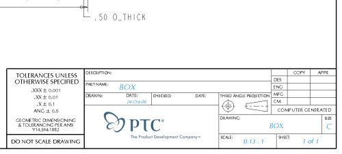
Zoom in ![]() on the title block in the lower right corner of the drawing.
on the title block in the lower right corner of the drawing.
|
|
Take note of the intelligence built into the format. Not only has the drawing name, scale and date been filled in, but these values are linked back to the source model and will change if changed in the model -- this insures complete accuracy of the information displayed. |
|
|
Also note the embedded jpeg logo image. You can use the OLE (Object-Linking Embedding) capabilities for inserting images and other file types into your drawings. |
![]() Refit the whole drawing in the window.
Refit the whole drawing in the window.
|
|
Take note of the shaded isometric view in the upper right corner. Using shaded views in drawings gives more options for communicating critical design information since colors can provide visual cues to help describe designs. By using shading, drawings can include more detail. |
|
Task 2. Create, move, and manipulate drawing views |
|
|
Let's look at how we can manipulate the views and create additional ones as needed. |
Select the FRONT view so that it is outlined with a dashed red box
Press and hold the Right Mouse Button over the view and uncheck Lock View Movement.
With the FRONT view still selected, Press and Hold the Right Mouse Button over the view and move the view around.
Release the Right Mouse Button to place the view 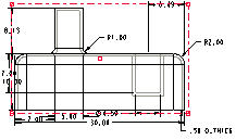
|
|
Notice the intelligence of the other views as they will continue to line up and follow the FRONT view accordingly. |
Return the FRONT view to its original position by using Edit, Undo from the menus (or use CTRL-Z)
|
|
Let add a projected view based off the Front view |
Select the FRONT view again,
Press and hold the right mouse button and select Insert Projection View.
Move the mouse around and notice that you have 4 possible projection options.
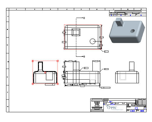
Select a point to the left of the FRONT view. The view will look similar to the figure below.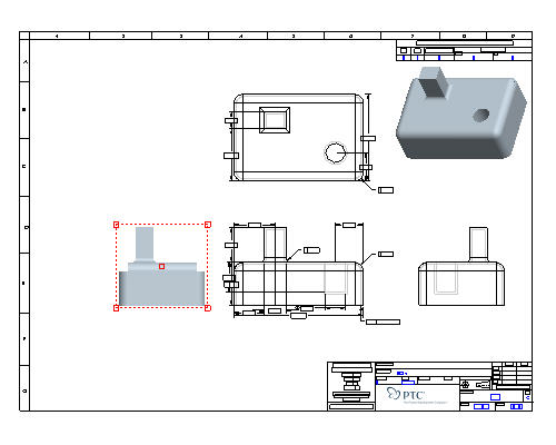
With the new view still selected, press and hold the right mouse button and select Properties. To change the properties on more than one view at a time, hold down the CTRL key while selecting them and then access the Properties window from the right mouse button menu. This can include determining visible areas, scaling, defining cross-sections, showing the model in various states, and aligning and setting the view origins.
![]()
Select the View Display Category in the Drawing view dialog box , change the Display Style from Follow Environment to Hidden. Follow EnvironmentUses the setting from Tools > Environment > Display Style or one of the view display style icons (
![]()
![]() Wireframe,
Wireframe, ![]() Hidden Line,
Hidden Line, ![]() No Hidden,
No Hidden, ![]() Shaded) in the Pro/ENGINEER graphics window.
Shaded) in the Pro/ENGINEER graphics window. 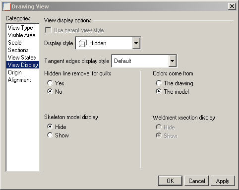
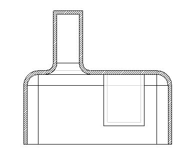
Click Apply from the Drawing View dialog box. The view will appear similar to the figure below. (Move the Drawing View dialog box if necessary to see the changes)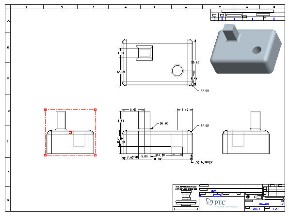
|
|
Create a cross-section of the new view we just created |
Select the Sections category in the Drawing View dialog box.
Choose 2-D cross section, and click Add Section ![]() .
.
Select section A (which is pre-defined in the part) from the Name drop-down.
Click Apply.
|
|
You can also modify the cross-hatching for certain materials or preferences. |
Scroll the section definition window all the way to the right.
Click on the empty "Arrow Display" box to activate it.
Select the TOP VIEW from the drawing window.
Click OK. Cross-section and view arrows can also be added by selecting the view and and choosing Insert, Arrows... from the drop-down menus (or by using the right mouse button menu to choose Add Arrows)
![]()
|
Task 3. Create, move and manipulate drawing details |
|
|
Most of the work done when creating drawings involves detailing. When you see the model dimensions on the drawing courtesy of the drawing template, many times you will need to move them around, clean them up and even delete existing or create new dimensions. |
Zoom-In ![]() to the FRONT and RIGHT views as shown (Click the Right Mouse Button to cancel the zoom function).
to the FRONT and RIGHT views as shown (Click the Right Mouse Button to cancel the zoom function).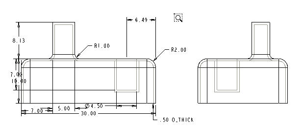
|
|
Following any zoom action, always click the Right Mouse Button (or choose Select Items |
Select the vertical 7.00 dimension on the front view (it will highlight in red).
Hold down the Right Mouse Button and choose Move Item to View.
Select the RIGHT view to move the dimension to the Right view.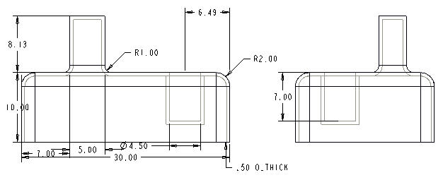
Select the vertical height dimension of 10.00.
|
|
With a dimension selected, the cursor changes shape to indicate what motion will be performed by holding down the Left Mouse Button and dragging: |
Hold down the Left Mouse Button and drag 10.00 dimension farther away from or towards the geometry.
Select and drag the 10.00 dimension up and down (notice the center snapping).
|
|
Center Gravity: Dimensions are automatically centered between the witness lines and when dimensions are moved, they snap to this centered location. This "gravity" location aids in placement. |
With the 10.00 unit dimension still highlighted, press and hold the Right Mouse Button and select Flip Arrows from the pull down to change the direction of the arrows.
Repeat the Flip Arrows command to switch the arrows back.
With the 10.00 unit dimension still highlighted, hold down the CTRL key and select the 8.13 dimension (the height of the protrusion).
|
|
Multi-select items by holding down the CTRL key and selecting the items. |
Press and hold Right Mouse Button and select Align Dimensions from the pull down.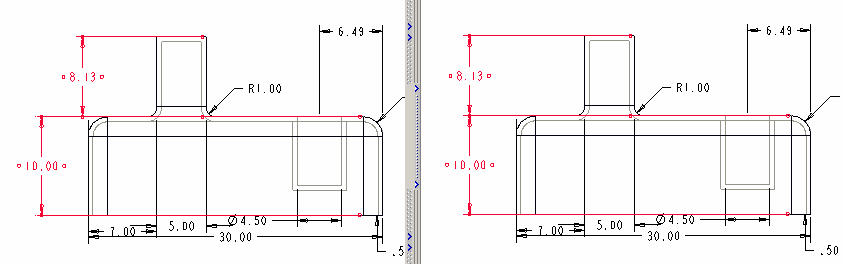
Select the FRONT view.
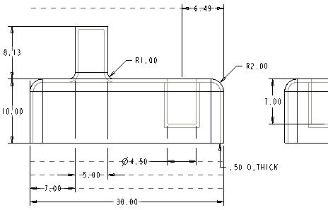
Press and hold Right Mouse button and select Cleanup Dimensions from the pull down. A dialog box will pop-up similar to the figure below.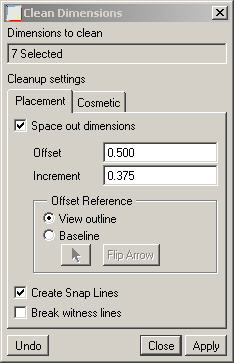
Choose the options and type in the values as shown in the figure above.
Clidk Apply and Close. Notice how this view can be quickly cleaned up.
|
|
To use this technique on multiple views, by first multi-selecting the views and then doing a Cleanup Dimensions to drastically reduce the amount of manual effort normally involved. |
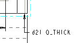
Select Info from the pull down menu at the top of the window and choose ![]() Switch Dims. This shows the symbol, or "parameter", for the dimensions.
Switch Dims. This shows the symbol, or "parameter", for the dimensions.
|
|
Repeating |
|
|
Now let's add a parametric note that calls-out the wall thickness. |
Select Insert -> Note... from the drop-down menus.
Select Make Note from the menu manager and accept all the defaults.
Click a spot anywhere under the Left cross-section view as the desired note location and middle-click
Type THE WALL THICKNESS IS &D21 INCHES and click Accept ![]() or press Enter.
or press Enter.
|
|
This symbolic name may be different than shown above. If so ensure you enter in the correct symbolic name in the note creation box. |
Select Accept ![]() again as you are not creating another sentence.
again as you are not creating another sentence.
Click Done/Return from the menu manager.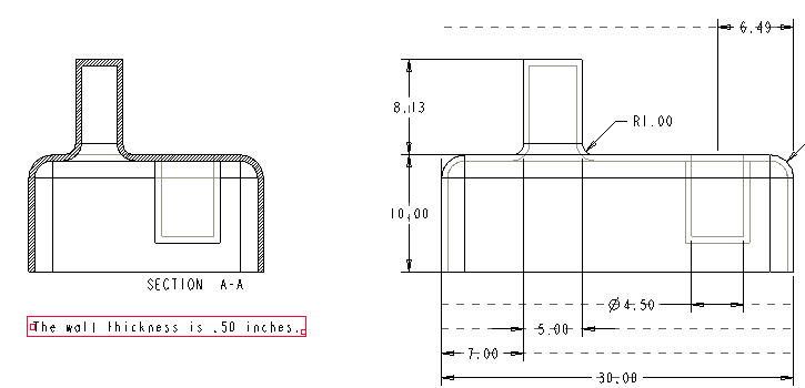
|
|
You can also add Ordinate Dimensions that use a single witness line with no leader, and are associated with a baseline reference. They are used mostly for flat plate or sheetmetal designs but we will illustrate an example of this capability on our box part. |
Insert, Dimension, Ordinate... from the drop-down menus.
Select the bottom edge as a baseline from the Right view as shown in the figure below.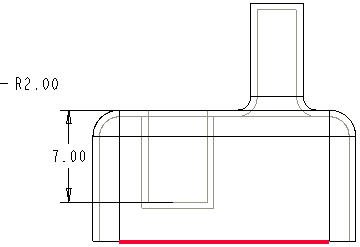
Select the two edges as shown below to create ordinate dimensions.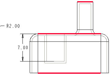
Place the cursor to the right of the view and click the Middle Mouse Button to place the dimensions.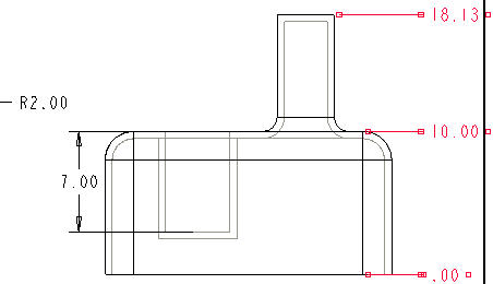
Click Return from the menu manager.
|
|
You can convert linear dimensions to ordinate dimensions and vice-versa. You can also have ordinate dimensions automatically created under Insert -> Dimension -> Auto Ordinate... as opposed to picking the individual entities in our exercise. This is extremely invaluable for flat plate and sheetmetal parts. |
Click Save ![]() from the main toolbar.
from the main toolbar.
Click OK.
Congratulations! You have successfully created your first part drawing.
|
Task 4. Make design changes in the model and drawing |
|
|
Now, let's investigate the effect of model changes on our drawing. |
|
|
One of the things that make Pro/ENGINEER the most powerful and respected CAD package on the market today is it's model-centric database architecture. In other words, "a single-source-of-truth" where all the physical properties are kept at the part level and that a change made anywhere gets reflected everywhere. |
Click Open ![]() from the main toolbar.
from the main toolbar.
Select the BOX.PRT from the Open dialog box.
Click Open and the BOX.PRT will open in a separate window.
From the model tree, Right Mouse Button select the Extrude 2 feature and select Edit.
Double-click the 8.13 dimension, change it to 4 and press Enter.
Click Regenerate ![]() the model.
the model.
Select the pulldown Window, BOX.DRW:1 to switch back to the drawing and see the changes.
|
|
Design changes can also be made from the drawing and the model will update. |
Select the note and press and hold Right Mouse button and select Edit Value from the pull down.
Type 0.2 and press Enter
Select Regenerate ![]() (again, notice how all the information is accurately updated on the drawing.
(again, notice how all the information is accurately updated on the drawing.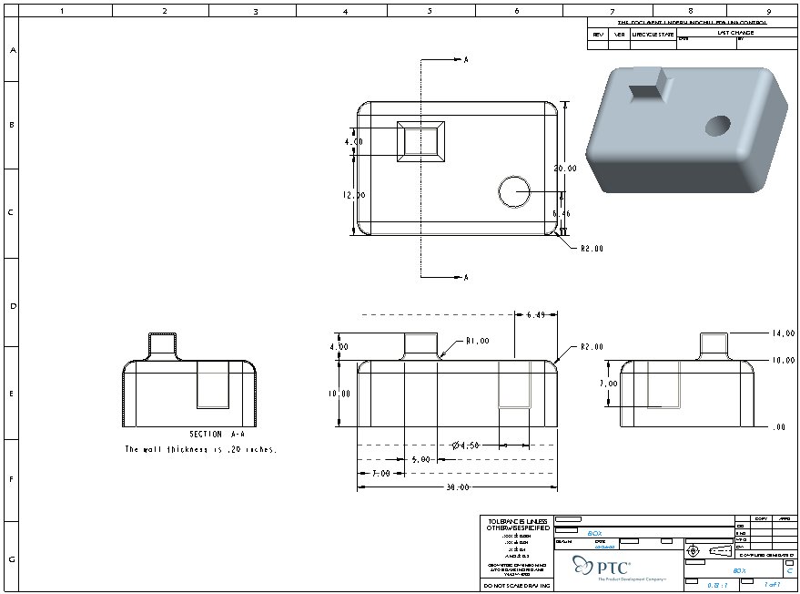
Select Window from the pulldown, BOX.PRT
Press and hold the Middle Mouse Button and rotate the part around. Notice how the model geometry updated.
File, Close Window ![]() to return to BOX.DRW.
to return to BOX.DRW.
Click Save Saving a drawing will also, by default, save any modified parts or assemblies it references.![]() from the main toolbar and click OK.
from the main toolbar and click OK.
![]()
File, Close Window ![]()
|
Task 5. Create a New Assembly Drawing |
|
|
Let's create a new drawing for the example assembly we created in our "Assembly" tutorial. |
Click the New ![]() icon on the main toolbar.
icon on the main toolbar.
Select Drawing as the Type.
Type EXAMPLE for the Name.
Make sure Use default template is checked.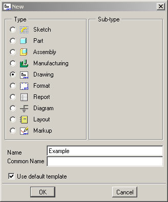
Click OK from the New dialog box.
Select Browse... for the Default Model and select EXAMPLE.ASM
Select Browse... for the Template and select C_ASSY.DRW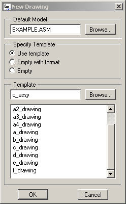
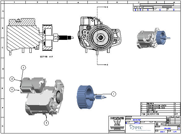
Click OK from the New Drawing dialog box. The template drawing will automatically layout the drawing.
If necessary, turn off the display of Datum Planes ![]() , Datum Points
, Datum Points ![]() , and Coordinate Systems
, and Coordinate Systems ![]() and Repaint
and Repaint ![]()
|
|
Use Redraw |
Zoom in ![]() on the lower right corner to observe the title block and the Bill of Material table.
on the lower right corner to observe the title block and the Bill of Material table.
Refit ![]() to see the whole page
to see the whole page
Select a call-out balloon (as shown below). Notice that the component highlights in the table.
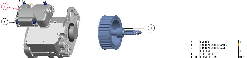
Select a different item in the table. Notice it will highlight the corresponding call-out.
|
|
Clean up the call-outs/BOM balloons both manually and automatically. |
Select the Hex Bolt call-out (#2)
Press and hold the Left Mouse Button over the selected call-out and drag it so that its leader line does not cross any other.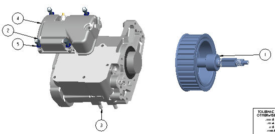
Select the exploded view.
Press and hold the Right Mouse Button and select Cleanup BOM Balloons.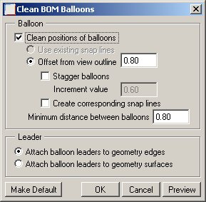
Accept the defaults and select OK to finish.
Click Save ![]() and click OK.
and click OK.
Congratulations! You have successfully created your first assembly drawing.
