This tutorial is intended to be used alongside Pro/ENGINEER Wildfire 3.0.
Please make sure that Pro/ENGINEER Wildfire 3.0 is installed on your machine before continuing. Your hosting Hands-on Workshop Application Engineer will have this set up for you. If not, please refer to the READ ME FIRST document.
Download the model files here. Save the zip file to your desktop.
Your web browser and Pro/ENGINEER can be resized and laid out as shown below to facilitate your experience.
 Positioning Tutorial Window |
It is recommended that you maximize the amount of working area on your screen by setting your monitor to the highest resolution setting, for example 1600x1200.
Use the Commands at the top of the page to navigate through the tutorial. Click Next to proceed to the next slide and Previous to return to the previous slide. Click Home to return to the beginning of the tutorial. If the page contains more information than the visible screen, a scroll bar will appear along the vertical side. Scroll through the entire contents before progressing to the next step.
You will see various icons throughout the tutorial:
There are several conventions used in this tutorial:
Have you ever had trouble deciding where to start on a new design? Should you start by building up individual parts and assembling them together? If so, which part should be the first part in the assembly? What happens if that first part needs to be replaced? These questions all stem from the fact that most 3D modeling CAD softwares today support a bottom up approach to creating 3D assemblies. The term bottom up typically means that users are creating individual parts and then assembling these parts together to create the finished design. This approach is counter to how most designers would like to work.
Most designers would like to start by creating some sort of layout of the new design from a high level and then detail the individual parts as the design progresses. Pro/ENGINEERs Advanced Assembly eXtension provides the tools to support this design process. These tools include functionality for creating a product structure prior to any geometry creation, skeleton model functionality for 3D layouts and interface geometry creation, data sharing features to communicate interface and other design information to lower levels, and a notebook for global parameters and placement datums.
PTC has also worked with a wide variety of customers in order to determine the best process to use in conjunction with the tools mentioned above that provide a robust method of using Pro/ENGINEER for top down design. The process involves using the following steps:
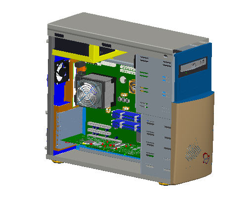
This tutorial will demonstrate how to use Advanced Assembly eXtension (AAX) to setup an assembly from the top down using the computer model shown on the first page. For the sake of simplicity the step of capturing specifications will be discussed at the end of the tutorial.
Step 1: Build a High Level Assembly Product Structure
Step 2: Define and Configure Design Framework using a Skeleton Part
Step 3: Develop Space Claims and Interference Geometry in the Skeleton Part
Step 4: Assemble the Sub-Assemblies to the Skeleton Part
Step 5: Develop the Lower Level Power Supply Skeleton Part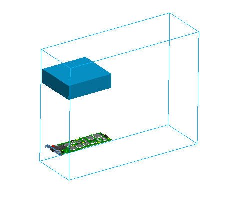
Step 6: Create a Publish Geometry to Distribute Interface Geometry to a Lower Level Skeleton
Step 7: Define the Structure of the Power Supply Subassembly
Step 8: Detail the Design of the Power Supply Mounting Bracket
Step 9: Review Top Level Assembly and Continue Design
Step 10: Propagate a Change to the Mounting Point Location in the Upper Level Skeleton to the Power Supply Assembly
Step 11: Capturing Design Specification using a Notebook
Step 12: Associating a Notebook to Parts and Assemblies
Step 13: Utilizing Global Datums for Assemblies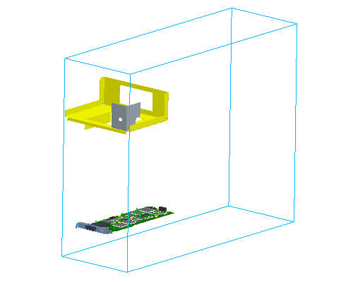
As an alternative to having this open along-side Pro/Engineer, you can also view a printable version by clicking here.
|
Task 1. Build a High Level Assembly Product Structure |
Start Pro/ENGINEER Wildfire 3.0 if necessary.
If Pro/ENGINEER is already running ensure all windows are closed, and all items from the previous exercise are erased from memory.
In the Navigator Folder Browser ![]() , browse to the following folder C:\HANDS-ON_WF3\AAX_TOP_DOWN_TUTORIAL
, browse to the following folder C:\HANDS-ON_WF3\AAX_TOP_DOWN_TUTORIAL
Click New ![]() icon from the main toolbar.
icon from the main toolbar.
In the New dialog box, select Assembly radio button and enter COMPUTER as the name.
Click OK from the dialog box.
|
|
Default templates are used when a new part or assembly is created. The default template is an initial design model that contains default features, layers, views, parameters and units. |
The new assembly will show three default planes to work from, a default coordinate system showing the assemblies 0,0,0 location, and a spin center for the model.
|
|
Now that an assembly exists, the next step will be to create the product structure. For the computer, this structure will include a chassis, mother board, graphics board, and hard drive sub-assemblies. |
Click Create Component ![]() icon on the Feature toolbar to create a new component.
icon on the Feature toolbar to create a new component.
In the Component Create dialog box, click the Subassembly radio button and enter CHASSIS for the name of the subassembly.
Click OK from the dialog box.
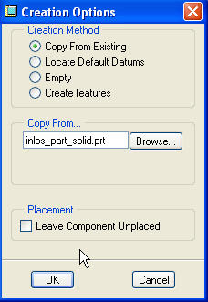
In the Creation Option dialog box, click Copy from Existing for the creation method and click Browse to copy from a template.
Select the INLBS_ASM_DESIGN.ASM and click Open in the Choose Template dialog box.
|
|
The Copy From Existing functionality allows a user to reference a start part for the base creation of a new model. Pro/ENGINEER load point (typically C:\Program Files\PTC) contains a sub-directory called templates that contains default templates. A config.pro option can be set to the location of of the template models. |
In the Creation Option dialog box under Placement, check Leave Component Unplaced check box. We will set a place holder in the model tree for the subassembly and place the assembly later.
Click OK from the Creation Options dialog box.
|
|
The Chassis assembly has been placed in the model structure with a special icon. This ability to "Leave Components Unplaced" is only available with AAX. |
Click Create Component ![]() icon on the right side toolbar to create a new component.
icon on the right side toolbar to create a new component.
In the Component Create dialog box, click the Subassembly radio button and enter MOTHERBOARD for the name of the subassembly.
Click Create Component ![]() icon on the right side toolbar to create a new component.
icon on the right side toolbar to create a new component.
In the Component Create dialog box, click the Subassembly radio button and enter HARD_DRIVE for the name of the subassembly.
Click OK from the dialog box and click OK from the Creation Options dialog box.
Click Create Component ![]() icon on the right side toolbar to create a new component.
icon on the right side toolbar to create a new component.
In the Component Create dialog box, click the Subassembly radio button and enter POWER_SUPPLY for the name of the subassembly.
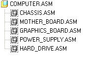
Click OK from the dialog box and click OK from the Creation Options dialog box. The Model Tree should appear like the following image.
|
|
Now that some new sub assemblies have been created, some sub assemblies subassemblies need to be added to the product structure. For this example, an existing graphics board sub-assembly will be added. |
Click Insert > Component >Include from the pull down menus.
In the Open dialog box, select GRAPHICS_CARD.ASM and click Open.
|
|
Notice that the graphics_card.asm file has been added to the product structure but has not been placed in the assembly. The subassembly structure can be expanded to investigate the components in the assembly, but the user does not have to place the subassembly in the top level assembly. The "Include" functionality is only available with AAX. |
Click Save ![]() from the main toolbar.
from the main toolbar.
|
Task 2. Define and Configure Design Framework using a Skeleton Part |
|
|
The next step in the top down design process is to develop space claim and interface information in the assembly, but in which model should that geometry be created? If assembly level features are used, volumes can not be generated and the user would need to worry about the order of feature creation. Ideally, all the interface and space claim information would automatically be placed prior to any actual component models. This is the exact purpose of a skeleton. Skeleton models act as a 3D layout for your design. With AAX, the user has the ability to create these special models that are automatically reordered to the first component in the assembly, are filtered out of BOMs, filtered out of mass property calculations, and can easily be excluded from drawing views. |
Click Create Component ![]() from the Feature toolbar to create a new component.
from the Feature toolbar to create a new component.
In the Component Create dialog box, select the Skeleton Model radio button as the type.
Accept the default name and click OK. The Default name for the model is assembly name_skel0001. This default naming convention makes it easy to identify skeleton models from the PDM or file system.
![]()
In the Creation Options dialog box, select Copy From Existing for the creation method and click Browse to copy from a template.
Select INLBS_PART_SOLID.PRT and click Open in the Choose Template dialog box.
Click OK from the Creation Options dialog box.
|
|
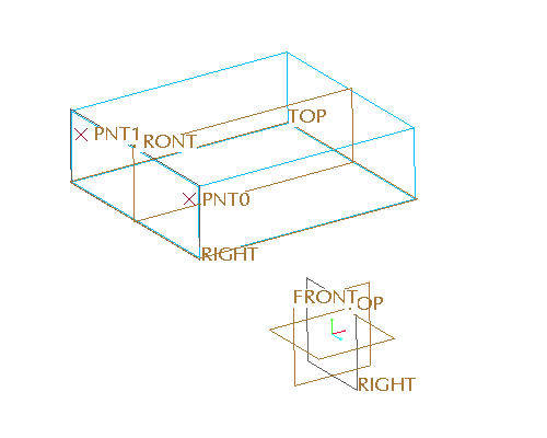
Notice that a new skeleton model has been added to the assembly and was automatically reordered as the first component in the assembly. Also, notice that the assembly has the default assembly datum planes and the default skeleton datum planes. The ability to create skeleton models is only available with AAX. |
Click the Show pull down menu from the model tree and select Layer Tree.
Select the 01_ASM_DEF_DTM_PLN layer and user the right mouse button pop up menu to select Hide.

Repaint the screen by selecting the Repaint ![]() icon.
icon.
Select Show from the pull down menu in the model tree and switch back to Model Tree.
|
Task 3. Develop Space Claims and Interference Geometry in the Skeleton Part |
|
|
Next, the geometry that represents the overall size of the computer will be developed in the skeleton model. By creating a simple overall volume of the computer in the skeleton model, packaging studies can be done without developing complex models. |
Select the COMPUTER_SKEL001.PRT from the model tree and use the right mouse button pop up menu to select Activate.
|
|
With the skeleton model activated, all features created will now be part of the skeleton model |
Start the Sketch Tool ![]() from the feature toolbar.
from the feature toolbar.
Select the FRONT datum plane as the sketching plane.
Click Sketch in the Sketch dialog box.
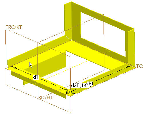
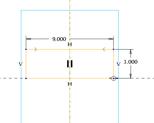
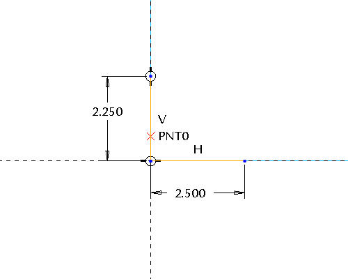
Sketch a simple Rectangle ![]() at the intersection of the two datum planes and dimension as shown below.
at the intersection of the two datum planes and dimension as shown below.
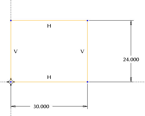
|
|
This section represents a side view of the computers overall size. |
Click Complete Sketch ![]() from the Sketcher toolbar.
from the Sketcher toolbar.
Select CTRL + D to reorient the model into default orientation.
Start the Extrude Tool ![]() from the feature toolbar.
from the feature toolbar.
In the dashboard, select the Both Sides ![]() as the depth option and enter an extrusion depth of 10 inches.
as the depth option and enter an extrusion depth of 10 inches.
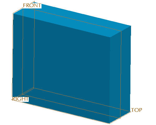
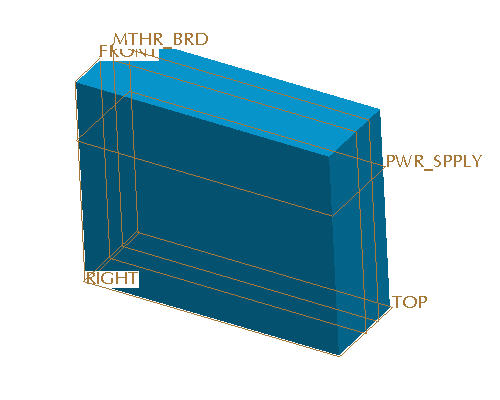
Click Complete Feature ![]() from the dashboard. The skeleton should now look like the picture shown below. Note for clarity the datums do not appear in the image below.
from the dashboard. The skeleton should now look like the picture shown below. Note for clarity the datums do not appear in the image below.
|
|
The blue color of the model is the default color for skeleton models in Pro/ENGINEER. This color makes it easy to quickly distinguish skeleton models from standard models. |

|
|
Now that a space claim for the computer exists, interface geometry and geometry used for assembling components can be created in the skeleton. By using the skeleton for assembly references the user can be assured that components will not lose any of their placement references as the assembly changes. Various datum features can be used for in the skeleton to create these references. |
Select anywhere in the graphics window to deselect all features.
Start the Datum Plane Tool ![]() from the feature toolbar to create a plane to place the power supply.
from the feature toolbar to create a plane to place the power supply.
Select the TOP datum plane to offset from.
In the Datum Plane dialog box, drag the offset handle upward so that the offset value is approximately 17 inches.
Click the Properties tab in the Datum Plane dialog box.
Enter a name of PWR_SPLY for the datum plane.
Click OK from the Datum Plane dialog box.
Select anywhere in the graphics window to de-select all features.
Start the Datum Plane Tool ![]() from the feature toolbar to create a plane to place the mother board.
from the feature toolbar to create a plane to place the mother board.
Select the FRONT datum plane to offset from.
In the Datum Plane dialog box, drag the offset handle approximately 2.5 inches away from center.
Click the Properties tab in the Datum Plane dialog box.
Enter a name of MTHR_BRD for the datum plane.
Click OK from the Datum Plane dialog box. The assembly should now look like the picture shown below.
Select anywhere in the graphics window to de-select all features.
Start the Datum Plane Tool ![]() from the feature toolbar to create a plane to place the graphic board.
from the feature toolbar to create a plane to place the graphic board.
Select the TOP datum plane to offset from.
In the Datum Plane dialog box, drag the offset handle upward approximately 4 inches.
Click the Properties tab in the Datum Plane dialog box.
Enter a name of GRPHCS_BRD for the datum plane.
Click OK from the Datum Plane dialog box.
|
Task 4. Assemble the Sub-Assemblies to the Skeleton Part |
|
|
There is now enough geometry in the top level skeleton to begin assembling or creating the sub-assemblies. In this step the existing graphics card subassembly will be placed in the model. |
Select the View Manager ![]() from the main toolbar.
from the main toolbar.
Select the Style tab from the View Manager dialog box.
|
|
Prior to placing the graphics card, it will be necessary to be able to see inside the computer skeleton in order to package the components. A "Style State" can be created to accomplish this. |
Select New from the Style tab.
Type WIRE_SKEL and press ENTER.
Select the Show tab from the EDIT:WIRE_SKEL dialog box and click Wireframe radio button selected selected as shown below.
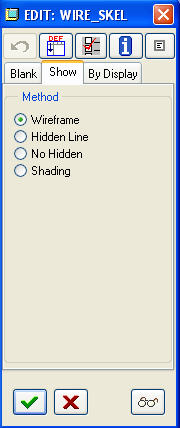
Select COMPUTER_SKEL0001.PRT from the graphics window or the model tree.
Click Accept Settings ![]() to finish creation of the style state.
to finish creation of the style state.
Verify that the computer skeleton is now shown in wire frame and select Close from the View Manager.
|
|
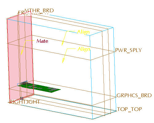
Now that it is possible to see inside the computer volume, the graphics card subassembly will be placed. |
Select the GRAPHICS_CARD.ASM from the model tree.
Press and hold the right mouse button to launch the pop up menu and select Edit Definition.
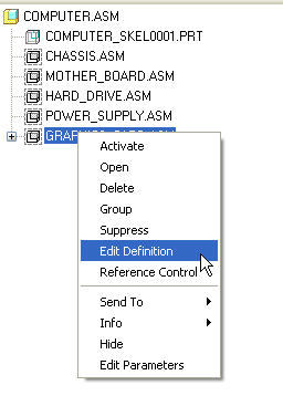
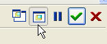
From the right hand side of the dashboard, select Same Window ![]() icon to show the component in the assembly window and deselect Separate Window
icon to show the component in the assembly window and deselect Separate Window ![]() icon to show the component in a separate window. The GRAPHICS_CARD will appear in the graphics window in yellow to represent the part being assembled.
icon to show the component in a separate window. The GRAPHICS_CARD will appear in the graphics window in yellow to represent the part being assembled.
Orient the model to spin the graphics board to approximately the position shown below. Roll the scroll button toward you to zoom in. Use SHIFT + MIDDLE-DRAG to pan the model to the center of the screen. Use MIDDLE-DRAG to rotate the model.
|
|
To select a surface, move the cursor over the surface until it turns blue. Then select the surface using the left mouse button. |
Click New Constraint in the Placement dialog box and edit the Constraint Type from Automatic to ![]() Align.
Align.
Select on the BASE_PLN datum plane in the graphics card.
Select on the GRPHCS_BRD datum plane in the skeleton.
Click New Constraint in the Placement dialog box and edit the Constraint Type from Automatic to ![]() Mate.
Mate.
Select on the BACK_PLN datum plane in the graphics card.
Select on the back vertical plane of the skeleton volume (highlighted in red below).
Notice that the dashboard report a STATUS: Fully Constrained. Select Complete Component![]() in the dashboard.
in the dashboard.
|
|
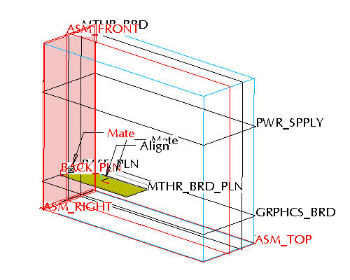
In the last step an existing assembly was placed by referencing geometry in the computer's skeleton model. In this step the power supply assembly needs to be developed from scratch. This process can start at the top level computer model by creating a skeleton model in the power supply subassembly. The power supply's skeleton model will consist of a space claim volume and interface geometry. |
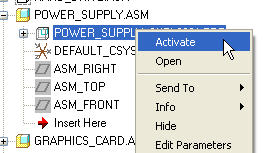
Select the POWER_SUPPLY.ASM from the model tree and use the right mouse button pop up menu to select Edit Definition.
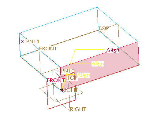
Click Placement from the dashboard, and edit the Constraint Type from Automatic to ![]() Align.
Align.
Select on the ASM_TOP datum plane of the power supply.
Select on the the PWR_SPLY datum plane of the computer skeleton.
|
|
To select a surface, move the cursor over the surface until it turns blue. Then select the surface using the left mouse button. |
Click New Constraint in the Placement dialog box and edit the Constraint Type from Automatic to ![]() Align.
Align.
Select on the ASM_FRONT datum plane of the power supply.
Select on the FRONT datum plane of the computer skeleton.
Click New Constraint in the Placement dialog box and edit the Constraint Type from Automatic to ![]() Mate.
Mate.
Select on the ASM_RIGHT datum plane of the power supply.
Select on the back vertical surface of the skeleton volume (highlighted in red below).
Notice that the dashboard report a STATUS: Fully Constrained. Select Complete Component![]() in the dashboard.
in the dashboard.
Next a space claim skeleton model will be created for the power supply subassembly. Select the POWER_SUPPLY.ASM subassembly from the model tree.
Use the right mouse button pop up menu to select Activate.
Select Create Component ![]() icon in the feature toolbar.
icon in the feature toolbar.
In the Component Create dialog box, select the Skeleton Model radio button as the type.
Accept the default name and click OK.
In the Creation Options dialog box, select Copy From Existing for the creation method and click Browse to copy from a template.
Select INLBS_PART_SOLID.PRT and click Open in the Choose Template dialog box.
Click OK from the Creation Options dialog box.
Expand the POWER_SUPPLY.ASM node in the model tree by selecting the + icon next to the subassembly name in the model tree. Notice that a skeleton model has been created.
Hold CTRL + left click to select ASM_FRONT, ASM_TOP, and ASM_RIGHT datum planes of the Power Supply assembly and use the right mouse button pop up menu to select Hide to clean up the display. Press and hold the CTRL
![]()

|
Task 5. Develop the Lower Level Power Supply Skeleton Part |
|
|
Now that the skeleton model has been created, features can be added to the model to develop a space claim volume and interface geometry. |
Select the POWER_SUPPLY_SKEL001.PRT from the model tree and use the right mouse button pop up menu to select Activate.
Select the RIGHT datum plane of the Power Supply skeleton.
Select the Extrude Tool ![]() icon from the feature toolbar.
icon from the feature toolbar.
Use the right mouse button pop up menu to select Define Internal Sketch.
Verify the Sketching Plane is RIGHT and Sketch Orientation TOP and reference TOP. Select Sketch from the Sketch dialog box or hit the middle mouse button to accept the defaults.
Click Datum Planes ![]() in the main toolbar to disable the display of datum.
in the main toolbar to disable the display of datum.
Sketch a simple Rectangle ![]() and dimension as shown below. Use a centerline to center the sketch.
and dimension as shown below. Use a centerline to center the sketch.
Click Complete Sketch ![]() from the Sketcher toolbar.
from the Sketcher toolbar.
In the dashboard, select the Blind ![]() as the depth option and enter an extrusion depth of 10 inches.
as the depth option and enter an extrusion depth of 10 inches.
Click Complete Feature ![]() from the dashboard. The Assembly should now look like the picture shown below. Note for clarity the datums do not appear in the image below.
from the dashboard. The Assembly should now look like the picture shown below. Note for clarity the datums do not appear in the image below.
|
|
The approximate size of the power supply has now been created and the placement of the power supply is controlled by the computer skeleton. The process of populating assemblies and creating skeletons could be repeated for the other sub-assemblies. This would create an optimal environment for performing packaging studies with a simple model. This process has also setup this model for very robust changes. |
|
|
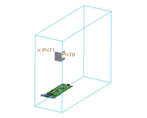
The power supply will need to be mounted to the chassis. This mount will be a simple fastener that will go through a hole on a bracket in the chassis subassembly and also go through a bracket on the power supply subassembly. Hence the parts that the hole will intersect will belong to two different sub-assemblies. What is the best way to handle this interface without creating unwanted external references? Where should the position of this hole be established? Should an assembly level feature be used? An assembly level feature would work, however there are no models to select for intersection at this stage of the design. Plus the user would need to worry about the order of feature creation and component placement to get this to work. Further, assembly level features can lead to performance degradation of the model. The best answer is to create the interface geometry at the top level skeleton and distribute that information to the appropriate lower level assemblies. In this example datum points will be used to represent the mounting holes for the power supply. These points will be created in the top level computer skeleton. |
Select the COMPUTER_SKEL0001.PRT from the model tree.
Use the right mouse button pop up menu to select Activate.
Click Datum Planes ![]() in the main toolbar to turn the display of datum planes back on.
in the main toolbar to turn the display of datum planes back on.
Select the Datum Point Tool ![]() icon in the feature toolbar.
icon in the feature toolbar.
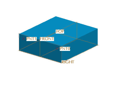
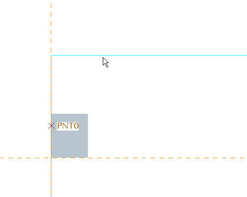
Select the surface shown below to place the datum point.

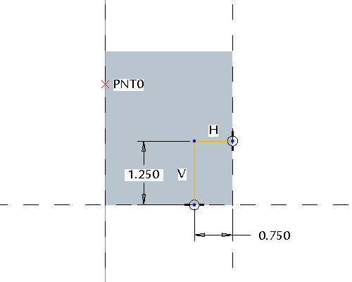
Drag the dimensioning handles to snap to the FRONT and TOP datum planes of the computer skeleton.
Drag the point to approximately the position shown below and select OK from the datum point dialog box.
With the point still selected, select the Mirror icon. ![]()
Select the FRONT datum plane of the computer skeleton model to mirror about.
Click Complete Feature ![]() from the dashboard to finish the mirror feature.
from the dashboard to finish the mirror feature.
|
Task 6. Create a Publish Geometry to Distribute Interface Geometry to a Lower Level Skeleton |
|
|
Two mounting points for the power supply have now been created. These mounting points can now be shared to other skeletons as needed using "data sharing" features. Data sharing features are special features in Pro/ENGINEER that are available only with the AAX module. These features understand their job is to share geometry between different models. They can be created as independent or dependent copies of the original geometry and this dependency can be toggled back and forth at any time. Further, these features will not fail if the parent object of the data sharing feature is not pulled into RAM during the Pro/E session. Hence, these features provide an excellent way to control and distribute interface information from top level assemblies to lower level sub-assemblies. In this example the mounting points will be "published" from the top level skeleton. Data sharing features can be created by either pushing geometry down to lower levels or pulling geometry from a higher level. |
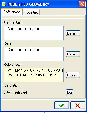
With the top level skeleton still active, select Insert > Shared Data > Publish Geometry from the pull down menu.
In the Published Geometry dialog box, select inside the References box so that it turns off white.
Press and hold the CTRL
|
|
Note: It's easiest to select a point by placing the cursor over the name of the point and then using the right mouse button to query through until the point is highlighted. |
Click Accept Setting ![]() from the Published Geometry dialog box.
from the Published Geometry dialog box.
Select the Settings pull down menu from the Model Tree and select Tree Filters.
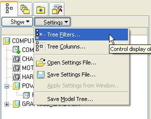
Select the check box next to Features to enable the display of features in the model tree.
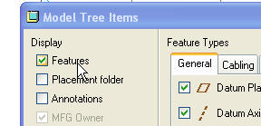
Select OK from the Model Tree Items dialog box.
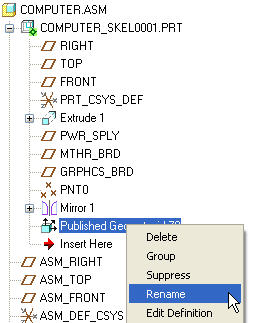
Expand the COMPUTER_SKEL0001.PRT model by selecting the + icon next to its name.
Select the Published Geometry feature and use the right mouse button pop up menu and select Rename. The published geometry feature will be renamed to something more descriptive.
Type PWR_SPLY_MNTS for the feature name.
|
|
The mounting points have been created and published at the top level skeleton. The next step is to pull that interface geometry down to the necessary lower level skeletons. In this example, the mounting point feature will be pulled down to the power supply subassembly skeleton so that the data can be used to design a mounting bracket. |
Expand the POWER_SUPPLY.ASM so that the skeleton model is visible if it is not already expanded.
Select the POWER_SUPPLY_SKEL0001.PRT from the model tree and select Activate.
Select Insert > Shared Data > Copy Geometry from the pull down menus.
|
|
Copy Geometry features (and all other data sharing features) are only available with the Advanced Assembly eXtension. |
Select one of the mounting points from the graphics window.
|
|
Notice that both points highlight when one is selected. This is due to the fact that by default, the scope of the copy geometry feature is set to only look for data that has been distributed. In other words, the selection will only select publish geometry features. This makes it very easy for a user to create a set of interface geometry as a publish geometry feature and copy that data into a lower level skeleton. Note: The ability to select only publish geometry features can be toggled off in the dash board by selecting the Published Geometry Only icon. |
Click Complete Feature ![]() from the dashboard to finish the copy geometry.
from the dashboard to finish the copy geometry.
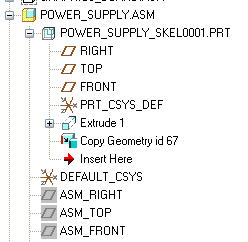
Expand the POWER_SUPPLY_SKEL0001.PRT. The model tree should look like the one shown below.
|
Task 7. Define the Structure of the Power Supply SubAssembly |
|
|
At this point there is enough information in the Power Supply subassembly to begin detail design of the parts. A volumetric space claim has been developed and interface information has been distributed to the subassembly's skeleton model. Hence, detail design could be done at the subassembly level and still assure the interfaces will be correct with limited or no interferences at the top level due to the space claim volume. In this step, a simple bracket will be designed at the power supply subassembly level and make use of the mounting point interface information. |
Select the POWER_SUPPLY.ASM from the model tree.
Use the right mouse button pop up menu to select Open. The power supply subassembly should look like the picture shown below.
|
|
Notice the subassembly now consists of skeleton with the space claim and mounting point information. It will be necessary to see inside this space claim to perform the detail design tasks. The view manager can be used for this requirement. |
Select the View Manager ![]() from the main toolbar.
from the main toolbar.
Select the Style tab from the View Manager dialog box if not already selected.
Select New from the Style tab.
Type WIRE_SKEL and press ENTER.
Select the Show tab from the EDIT:WIRE_SKEL dialog box and click Wireframe radio button selected selected as shown below.
Click Accept Settings ![]() to finish creation of the style state.
to finish creation of the style state.
Verify that the computer skeleton is now shown in wire frame and select Close from the View Manager.
Click Create Component ![]() from the Feature toolbar to create a new component. A simple bracket part will be created to demonstrate how parts can be created from an assembly level and utilize any interface geometry that has been passed down from the top level assembly.
from the Feature toolbar to create a new component. A simple bracket part will be created to demonstrate how parts can be created from an assembly level and utilize any interface geometry that has been passed down from the top level assembly.
In the Component Create dialog box, select the Part radio button as the type.
Type BRACKET for the part name and click OK.
In the Creation Options dialog box, select Copy From Existing for the creation method and click Browse to copy from a template. Note: The "Copy from Existing" function allows the user to use start parts even while creating parts at the assembly level.
![]()
Select INLBS_PART_SOLID.PRT and click Open in the Choose Template dialog box.
In the Creation Option dialog box under Placement, uncheck Leave Component Unplaced check box.
Click OK from the Creation Options dialog box.
Orient the model to spin the assembly to approximately the position shown below. Roll the scroll button toward you to zoom in. Use SHIFT + MIDDLE-DRAG to pan the model to the center of the screen. Use MIDDLE-DRAG to rotate the model.
Press and hold the CTRL
|
|
The component can be move independent of the assembly model by using the following mouse and key combinations.
|
Click Placement from the dashboard, and edit the Constraint Type from Automatic to Note: Ensure that the datum planes are aligned with zero offset by selecting the coincident icon if necessary. ![]() Align.
Align.
![]()
![]()
Select on the RIGHT datum plane in the new component.
Select on the RIGHT datum plane in the skeleton.
Click New Constraint in the Placement dialog box and edit the Constraint Type from Automatic to ![]() Align.
Align.
Select on the TOP datum plane in the new component.
Select on the TOP datum plane in the skeleton.
Click New Constraint in the Placement dialog box and edit the Constraint Type from Automatic to ![]() Align.
Align.
Select on the FRONT datum plane in the new component.
Select on the side surface of the skeleton model as shown below.
Notice that the dashboard report a STATUS: Fully Constrained. Select Complete Component![]() in the dashboard to finish the component creation and placement.
in the dashboard to finish the component creation and placement.
|
Task 8 . Detail the Design of the Power Supply Mounting Bracket |
|
|
Note that the mounting point from the skeleton is visible and therefore could help in determining the size for the bracket. |
Select the BRACKET.PRT from the model tree.
Use the right mouse button pop up menu and select Activate.
Select the TOP datum plane of the bracket from the graphics window.
Select the Extrude icon. ![]()
From the dashboard select the Thicken Sketch icon. ![]()
Use the right mouse button pop up menu to select Define Internal Sketch.
Select Sketch or click the middle mouse button to accept the defaults of the sketch orientation.
Turn off the display of datum planes. ![]()
Sketch the section shown below.
|
|
Note that the mounting point from the skeleton is visible and therefore could help in determining the size for the bracket. |
Click Complete Sketch ![]() from the Sketcher toolbar.
from the Sketcher toolbar.
In the dashboard, select the Blind ![]() as the depth option and enter an extrusion depth of 3 inches.
as the depth option and enter an extrusion depth of 3 inches.
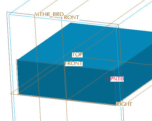
Click Complete Feature ![]() from the dashboard. The mounting point geometry can now be copied down into the part. Although a hole could be created on the point in the skeleton, better practice would be to use the data sharing features to copy the point geometry into the part.
from the dashboard. The mounting point geometry can now be copied down into the part. Although a hole could be created on the point in the skeleton, better practice would be to use the data sharing features to copy the point geometry into the part.
Select Insert > Shared Data > Copy Geometry from the pull down menus.
Deselect the Publish Geometry Only icon. ![]()
Select the References tab from the dashboard (It should be in red).
Select in the References box so that it changes to off white as shown below.
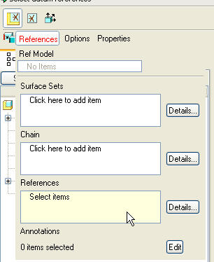
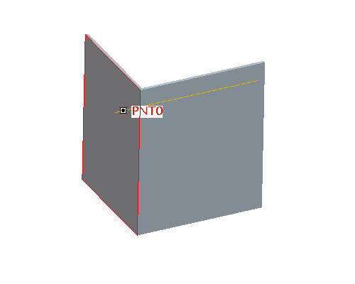
Select PNT0 from the graphics window.
Click Complete Feature![]() from the dashboard to finish the feature.
from the dashboard to finish the feature.
|
|
There is now enough geometry and interface information in the mounting bracket to finish the detailed design of the bracket outside the context of any assembly. Without using top down design and the tools available with the AAX module, this may have been where the design for this bracket started. If that happened, no relative size or interface information would have been available to the designer. Further, the bracket may have been assembled to another part rather than a skeleton model which sets up the potential for lost references. Hence, there are many advantages to using the top down design process outlined in this tutorial. |
Select the BRACKET.PRT from the model tree.
Use the right mouse button pop up menu and select Open.
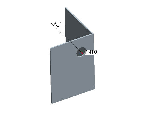
Select the Datum Axis ![]() icon from the Feature toolbar.
icon from the Feature toolbar.
Hold down the CTRL
Select OK from the Datum Axis dialog box.
With the axis still selected, select the Hole Tool ![]() icon from the Feature toolbar.
icon from the Feature toolbar.
Use the right mouse button pop up menu to select Secondary Reference Collector.
Select the front surface as shown in the picture above.
Set the diameter to .5 inches.
In the dashboard, select the Thru All ![]() as the depth option.
as the depth option.
Click Complete Feature ![]() from the dashboard to finish the feature. The part should now look like the picture shown below.
from the dashboard to finish the feature. The part should now look like the picture shown below.
|
Task 9. Review Top Level Assembly and Continue Design |
|
|
The basic design for the power supply mounting bracket has now been completed. By using a top down design methodology supported by the tools provided in the Advanced Assembly eXtension the design process flowed from creating a top level assembly first, developing the product structure prior to any geometry creation, setting up a 3D layout in a skeleton model, creating the sub-assemblies, and finally creating the detailed parts. In this step the status of the top level assembly will be reviewed and some additional features will be added to the mounting bracket. |
Select Window > COMPUTER.ASM from the pull down menus.
|
|
Notice that the Power Supply subassembly has been updated to include the new bracket part and the hole in the part is lined up with the mount point as expected. To better see the bracket part the power supply skeleton can be hidden. |
Select the POWER_SUPPLY_SKEL0001.PRT from the model tree.
Use the right mouse button pop up menu to select Hide. The assembly should now look like the picture shown below.
|
|
At this point the designer may decide that additional features need to be added to the mounting bracket. This can be done by simply activating the mounting bracket at this level and continuing the design. Many users choose not to work on design parts at high level assemblies due to the fact that unwanted external references can be created accidentally. An external reference is made when a feature references geometry from a different part or assembly other than the part the feature is created in. The Advanced Assembly eXtension provides a reference control tool to eliminate the possibility of creating unwanted external references. By using this tool the user can work on a model at a higher level assembly as if the user was working on the part by itself. |
Select Tools > Assembly Settings > Reference Control from the pull down menus. This will bring up the External Reference Control dialog box to set reference controls prior to creating a new cut feature in the bracket.
|
|
The Reference Control tool is only available with the Advanced Assembly eXtension. |
Notice that by default, the objects a feature is allowed to reference is set to All. This setting implies that, for example, the user could reference any other model when creating a feature inside the bracket. For this example no references will be allowed to be created while working on the bracket.
Select None from the External Reference Control dialog box.
|
|
Notice that the scope of the references can be set to be only within the subassembly (that would be the power supply subassembly in this example) or the skeleton model. |
Select the Selection tab in the External Reference Control dialog box.
Select the grey color button next to the Change Color of Allowed for Backup as shown below. This will bring up the Color Editor dialog box.
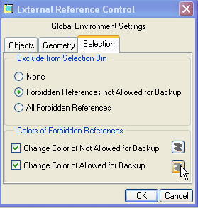
Change the color settings to red as shown below.
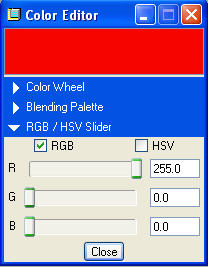
Select Close from the Color Editor dialog box.
Select OK from the External Reference Control dialog box.
Select the BRACKET.PRT from the model tree.
Use the right mouse button pop up menu to select Activate.
Select the Extrude Tool ![]() icon from the feature toolbar to create a new cut after the reference control has been set.
icon from the feature toolbar to create a new cut after the reference control has been set.
|
|
Notice that when the extrude icon is selected all other models in the assembly turn red. This is due to the fact that all other models are "out of scope" as defined by the External Reference Control tools. |
Select the Remove Material ![]() icon from the dashboard.
icon from the dashboard.
Use the right mouse button pop up menu to select Define Internal Sketch.
Verify the Sketching Plane is FRONT and Sketch Orientation TOP and reference TOP. Select Sketch from the Sketch dialog box or hit the middle mouse button to accept the defaults.
|
|
This datum plane can be selected from the model tree under the BRACKET.PRT or by turning on the display of datum planes and using the right mouse button to query to the datum plane. |
Click Datum Planes ![]() in the main toolbar to display of datum.
in the main toolbar to display of datum.
Select OK or click the middle mouse button to accept the default sketch orientation
Once in the sketcher, select Sketch > References from the pull down menus.
Select the top surface of the skeleton model for a reference as shown below.
|
|
Notice that a warning message is shown in the message window stating "Reference restricted by Environment scope was selected. Confirm to copy entity". This is due to the reference control setting of "None" setup earlier. The user could copy this reference into the part if desired. In this example no external references are desired so the action will be canceled. |
Select Cancel from the menu manager.
Select the right side surface of the bracket for a sketcher reference as shown below.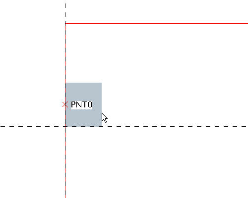
|
|
Notice that since the selected surface is owned by the bracket part, no warning messages are displayed. |
Select Close from the References dialog box.
Sketch the section shown below using Lines ![]() and Dimensions
and Dimensions ![]() .
.
.
Click Complete Sketch ![]() from the Sketcher toolbar.
from the Sketcher toolbar.
In the dashboard, select the Thru All ![]() as the depth option.
as the depth option.
|
|
The depth can also be set to through all by moving the cursor over the depth handle in the graphics window and using the right mouse button pop up menu. |
Click Complete Feature ![]() from the dashboard to finish the feature.
from the dashboard to finish the feature.
|
Task 10. Propagage a Change to the Mounting Point Location in the Upper Level Skeleton to the Power Supply Assembly |
|
|
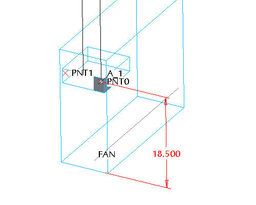
The computer assembly has now been setup for robust changes by using the top down design process and the functionality available within the Advanced Assembly eXtension. In this step the mounting point location for the power supply will be changed. How would this task be done without using top down design techniques? If there were multiple parts that needed to change due to the mounting point moving would that require changing parameters for features in multiple parts? How would alignment be assured if these features were dimensioned from different references? If external references were used (which is not recommended without using data sharing features) and no skeletons were used, how would the user determine what feature owns the required dimension? By using skeleton models and data sharing features the process of moving this interface geometry and the resulting changes in part level geometry has been simplified. Change the location of the mounting point. |
Expand the feature list of the COMPUTER_SKEL0001.PRT in the model tree if it is not already expanded.
Hit CTRL + A on the keyboard to ensure the top level assembly is active.
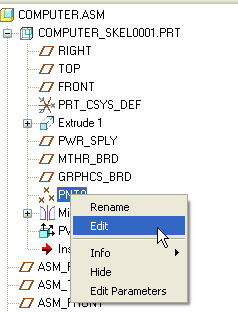
Select PNT0 from the model tree and use the right mouse button pop up menu to select Edit.
Select the vertical location dimension of the point and change it from approximately 19.2 to 18.25.
Select CTRL + G to regenerate the model.
Congratulations! This completes this tutorial. Proceed to the Optional Tasks to Capture and Associate Design Specifications using AAX.
|
|
Notice that the point moved down, the copied point in the power supply assembly also moved down, and the hole in the bracket part moved as well. This was all down without creating uncontrolled external references. In this example only one part has been modeled that references the mounting point location. In a real world design there may be multiple parts that utilize this mounting point location. The same process for utilizing the mounting point location in the bracket part could have been utilized for multiple parts and the resulting change would propagate to all parts. |
|
Task 11. Optional: Capturing Design Specification using a Notebook |
|
|
As mentioned in the introduction of this tutorial, the first step in a top down design process may be to capture design specifications. These specifications could include key parameters for the design and key location datums. This step was omitted at the start of the tutorial for simplicity sake. This step covers how these specifications could be captured using the Notebook tool provided with the Advanced Assembly eXtension and be used to control the models in the design assembly. If a key value like the height of the computer needed to be changed, how could this change be done without using a notebook? Certainly many different parts of the computer would be affected by this change including structural members of the chassis, sheet metal panels, and plastic bezels. Should the user change all the parts individually? Data sharing features could be used to pass some of the overall size geometry, but then user would then be required to use these features to set the size of the model. Data sharing features are typically better suited for interface geometry as shown earlier in this tutorial. Perhaps relations could be used. If so, at what level should the relations be written? If all the parts come together at the top level assembly, the only place to write these relations without using a notebook would be at the top level. What if a particular designer was responsible for only a subassembly of the computer and did not have the right to change the top level assembly? How would that designer tie their subassembly to the overall dimensions created at the top level? All these questions can be answered by using a notebook. In this step a sample notebook will be investigated and utilized in the computer model. |
Click Open ![]() from the main toolbar.
from the main toolbar.
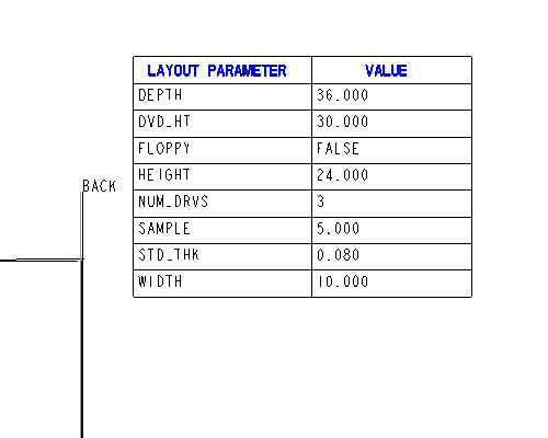
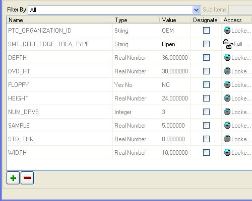
Select the COMPUTER.LAY file and select Open. A notebook may also be called a layout. These names are used interchangeably. These files have a .lay extension. New layouts can be created by selecting the Layout radio button in the New File dialog box. Notebook functionality is only available with the Advanced Assembly eXtension. Notice that a layout or notebook looks very similar to a drawing. Layouts can have formats just like drawings and contain only 2D information. The difference is that a layout references no Pro/ENGINEER models. Instead 3D models reference the layout. This layout contains a Pro/REPORT table showing the global parameters that exist in the layout and a couple simple sketches of the computer.
![]()
Select Tools, Parameters from the pull down menus to add a new parameter to the layout.
Select the ![]() icon from the parameters dialog box.
icon from the parameters dialog box.
Enter a name of SAMPLE for the parameter, ensure that it is a real number, and enter a value of 5.
Select OK from the parameters dialog box.
Select View > Update > Current Sheet from the pull down menus. Notice that the Sample parameter has now been added to the report table as shown below.
|
|
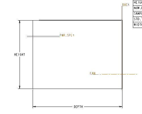
Notice that the layout also contains some key interface datums. These interface datums can be identified in different parts and assemblies. Once these datums are identified, they can be used to automatically assembly parts into an assembly. This functionality is very useful when assembling existing parts into new assemblies. For example, imagine if a fan model existed in a library and was placed in a variety of different assemblies. The central axis of the fan could be tied to a global datum from a layout. If that was done, the designer could simply create a fan axis in their new assembly and the library model would automatically be placed on this axis during assembly. |
Select Insert, Draft Datum, Plane from the pull down menus to add a new global datum plane to the layout.
Sketch a the PWR_SPLY datum by selecting the start and end points in the graphics window as shown below.
|
|
Drawing a datum plane in a layout is just like drawing a line. The location of the datum plane on the layout is not important. |
Select the blue arrow from the right side toolbar ![]() or click the middle mouse button to exit the datum drawing mode. The layout is now ready to be utilized by different parts and assemblies.
or click the middle mouse button to exit the datum drawing mode. The layout is now ready to be utilized by different parts and assemblies.
|
Task 12. Optional: Associating a Notebook to Parts and Assemblies |
|
|
Now that a layout (or notebook) has been created, the next step is to utilize the global parameters and datums defined in the layout on existing parts or sub-assemblies. For this example, an existing sheet metal part used in the chassis of the computer will be tied to the layout. |
Click Open ![]() from the main toolbar.
from the main toolbar.
Select the POWER_SUPPLY_TRAY.PRT file and select Open.
|
|
The first step to utilize the layout information is to "declare" the part to the layout. This will bring in all the global parameter and global datum information into the part. |
Select File > Declare from the pull down menus.
From the menu manager on the right hand side, select Declare Lay.
Select COMPUTER from the list of layouts.
|
|
A layout must be in session in order to be declared. |
Select Tools . Parameters from the pull down menu.
Scroll to the bottom of the list of parameters and notice that all the global parameters from the layout are now available in the part.
|
|
A good way to utilize these parameters is to write relations to part dimensions. If relations are used, the link back to the layout values can be quickly broken by simply commenting out or deleting the relations. Hence, the part can be tied to high level parameters or dimensions without creating these relations at higher level assemblies. |
Select Tools > Relations from the pull down menus.
Select the base wall of the part to show the dimensions as shown below.
|
|
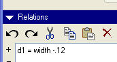
A relation can be written to set the d1 dimension as a function of the overall width of the computer. For this example, it will be assumed that the designer needs .060 clearance on each side of the computer. Hence, the d1 dimension should be the width - .12 |
Write a relation of d1 = width - .12 as shown below.
Select OK from the relations dialog box.
Select CTRL + G to regenerate the model or click the Regenerate ![]() icon in the main toolbar.
icon in the main toolbar.
|
|
Notice that the part has now grown in width. A global parameter is now in control of the overall width of the power supply tray. This process can be a useful technique if a designer does not want to work on the part in the context of the assembly, but does need critical design parameters about the overall design. Further, this sets the model up for robust and predictable change. |
Click Save ![]() from the main toolbar and OK.
from the main toolbar and OK.
|
|
Another example of using a notebook is to utilize any global datums that have been created in the notebook. In this example the PWR_SPLY datum plane created in the notebook in Step 9 will be used in the power supply tray sheet metal part. This will allow for automated assembly when this part is placed in the higher level assembly. |
Select File > Declare from the pull down menus.
Select Declare Name from the Declare menu.
Select the FRONT datum plane for the graphics window or the model tree.
Select Okay from the Direction menu to accept the default direction.
Enter a name of PWR_SPLY.
|
|
The name entered in this step must be spelled the same as the datum created in the layout in step 9. |
With the Declare Name menu still selected, select the FRONT datum plane from the graphics window or the model tree.
Select Okay from the Direction menu to accept the default orientation.
Enter a name of BACK for the datum. The datum planes should now be renamed on the screen and tied to global datum planes.

Click Open ![]() from the main toolbar.
from the main toolbar.
From the Open dialog box, select In Session ![]() icon.
icon.
Select the COMPUTER_SKEL0001.PRT file and select Open.
Select File > Declare from the pull down menus to associate the global datums at the skeleton level.
Select Declare Name from the Declare menu.
Select the COMPUTER layout from the Layout menu.
Select Declare Name from the Declare menu.
Select the PWR_SPLY datum plane from the graphics window or the model tree.
Select Okay from the menu to accept the default orientation.
Type PWR_SPLY for the datum name.
With the Declare Name menu still selected, select the RIGHT datum plane from the graphics window or model tree.
Select Flip from the menu to match the orientation shown below.

Select Okay from the menu to accept the new direction.
Type BACK for the datum plane name. This plane will represent the back plane of the computer. The skeleton model is now tied to global datums created in the layout.
Click Save ![]() from the main toolbar and OK.
from the main toolbar and OK.
|
Task 13. Optional: Utilizing Global Datums for Assemblies |
|
|
At this point both the power supply tray part and the top level computer skeleton have been tied to the layout. In this step the global datums will be utilized for assembly. |
Select Window > COMPUTER.ASM from the pull down menus.
Select Component Assemble ![]() icon on the Feature toolbar.
icon on the Feature toolbar.
In the dialog box, select the POWER_SUPPLY_TRAY.PRT and select Open. The new component will appear in yellow on the screen.
Select OK from the Open dialog box. Notice that the power supply tray comes in with two constraints already defined. This is due to the fact that Pro/ENGINEER has matched up the global datum planes declared to the layout of both the power supply tray and the computer skeleton.
|
|
Declaring global datums and auto assembling based on those declarations is only available with the Advanced Assembly eXtension. |
Select the Placement tab from the dashboard. Notice that two constraints already exist.
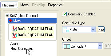
Select New Constraint from the dashboard as shown above.
Select the RIGHT datum plane from the POWER_SUPPLY_TRAY.PRT and the FRONT datum of the computer skeleton.
Select Complete Component ![]() to finish the component placement.
to finish the component placement.
Click Datum Planes ![]() in the main toolbar to disable the display of datum planes. The assembly should now look like the picture shown below.
in the main toolbar to disable the display of datum planes. The assembly should now look like the picture shown below.
Click Save ![]() from the main toolbar and OK.
from the main toolbar and OK.
Congratulations! This completes the Optional portion of this tutorial.
|
|
By using global parameters and datum planes, the power supply tray snapped right into place with only one constraint required and was also the appropriate width. This was done without ever opening the top level assembly. Not only can this be a dramatic performance tool, but it also provides a mechanism to make global changes to a design from a single source. |
Conclusion:
Pro/ENGINEER's Advanced Assembly eXtension provides a broad set of tools to more effectively design a product from the "top down". These tools can compliment a process that can more easily allow for concurrent engineering and robust changes to models. Hence, these tools can dramatically reduce errors and design cylce times.