Example: Split Surfaces
You can use the Split Surfaces check box to control the splitting of one or more top and bottom surfaces to create matching surfaces. These are typically the surfaces that you want to mesh with brick and wedge type elements.
In the following figure, a thin solid control is defined with a, b, and c as the top surfaces and d as the bottom surface. Three surface pairs are created as a-d, b-d, and c-d.
When you select the Split Surfaces check box, the bottom surface d is split into three surfaces d1, d2, and d3. These surfaces form 3 one-one pairs with the top surfaces as shown below. Compatible surface meshes are created and the surface meshes are extruded to form bricks and wedges elements.
If you clear the Split Surfaces check box, you can select only one surface each on the top and bottom surfaces. None of the surfaces are split to create imprints of the opposing surface. This is useful for cases like L-sections or thin solid controls with nonperpendicular side surfaces.
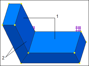
In the following example, two thin solid controls are defined. On meshing, only 2 brick elements are created as shown below.
1. Two brick elements created on meshing
2. A pair of opposing surfaces used to define one thin solid control
For the same model, if you select the Split Surfaces check box, a small region near the corner has to be filled with tetrahedral elements as shown in the following figure:
1. 2 brick elements created on meshing
2. 6 tetrahedral elements created in this region on meshing
To avoid the region with tetrahedral elements, clear the
Split Surfaces check box. In this way, no surfaces are split. However, the surfaces must satisfy the
requirements to create a compatible surface mesh in AutoGEM.


