Editing Bend Reliefs
Use the Edit Bend Relief tool to edit existing bend reliefs or introduce new bend reliefs by selecting relevant geometry in your model.
Follow the steps below to edit bend reliefs.
4. Click

.
Selecting Bend Reliefs
1. In an open sheet metal part with bend reliefs, click
Flexible Modeling >
 Edit Bend Relief
. The
Edit Bend Relief tab opens.
2. Select the bend reliefs to edit ,or click

to select bend reliefs automatically.
Changing the Type of Bend Relief
1. To change the bend relief shape, select a different type from the

list, or use the
Shape tab.
◦ Rip—The selected bend reliefs are edited to rip reliefs with no dimensions.
◦ Rectangular—The selected bend reliefs are edited to rectangular reliefs with width and depth dimensions.
◦ Obround—The bend relief is edited to an obround relief with width and depth dimensions.
◦ [<Parameter Value>]—Edits all selected bend reliefs to the SMT_DFLT_BEND_REL_TYPE parameter value.
2. To set the depth type applicable to the relief selected, select a bend relief depth type from the

list or the
Shape tab list.
◦ Blind—Creates a the bend reliefs with a depth set in the adjacent box or the box below.
◦ Up to Bend—Creates the bend reliefs up to the bend line.
◦ Tangent to Bend—Creates the bend reliefs tangent to the bend.
◦ [<Parameter Value>]—Uses the SMT_DFLT_BEND_REL_DEPTH_TYPE parameter value.
3. To set the value for the relief depth for the Blind option, use one of the following options.
◦ Thickness—Use a default length that is equal to the thickness of the sheet metal wall.
◦ 2.0 * Thickness—Use a default length that is twice the thickness of the sheet metal wall.
◦ [<Parameter Value>]—Uses the SMT_DFLT_BEND_REL_DEPTH parameter value.
◦ Type a value—Use the absolute value that you type in the box.
4. To set the length type of the bend relief, select an option from the list or the Shape tab list.
◦ Blind—Creates the bend reliefs with a length of the specified value.
◦ To Next—Creates the bend reliefs with a length to the next surface.
◦ Through All—Creates the bend reliefs through all surfaces.
◦ [<Parameter Value>]—Uses the SMT_DFLT_BEND_REL_LENGTH_TYPE parameter value.
5. To set the value for the relief length for the Blind option, use one of the following options.
◦ Thickness—Use a default length that is equal to the thickness of the sheet metal wall.
◦ 2.0 * Thickness—Use a default length that is twice the thickness of the sheet metal wall.
◦ [<Parameter Value>]—Uses the SMT_DFLT_BEND_REL_LENGTH parameter value.
◦ Type a value—Use the absolute value that you type in the box.
6. To set the bend relief width, use one of the following options in the

box or the width box in the
Shape tab.
◦ Thickness—Use a default width that is equal to the thickness of the sheet metal wall.
◦ 2.0 * Thickness—Use a default width that is twice the thickness of the sheet metal wall.
◦ [<Parameter Value>]—Uses the SMT_DFLT_BEND_REL_WIDTH parameter value.
◦ Type a value—Use the absolute value that you type in the box.
Removing and Recreating Bend Reliefs
Use the Options tab to set removal settings for a selected bend relief.
1. Select a bend relief from the Bend Reliefs list.
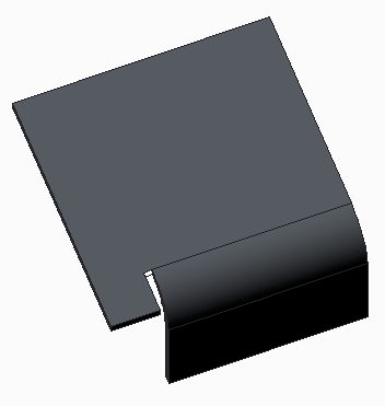
In the figure below, there is a bend relief before editing.
2. Select up to 2 boundary surfaces.
3. To use a system determined method to close the relief, click to select the Default removal check box.
In the figure below the highlighted surface was selected to remove using default removal. The new bend relief was created as a rectangular relief, Up to Bend with a width of 0.50.
4. To set the method for closing the relief, select an option from the Removal method list.
◦ None—Does not remove existing geometry.
◦ Tangent—Extends boundary surface to make it a planar surface tangent to the original surface.
◦ Same—Extends boundary surface by continuing it past its original boundaries and keeping the same type of surface.
◦ Linear—Connects boundary surface linear to the selected removal reference.
5. To set the reference used to connect between the bounding surface of the relief and the wall, select an option from the Removal reference list.
◦ Up to Bend Side—Extends the bounding geometry up to the plane that intersects the normal to the bend attachment and the bend side.
◦ Up to Bend Start—Extends the boundary surface up to the bend start.
◦ Up to Bend Axis—Extends the bounding geometry up to the bend axis.
◦ Up to Bend End—Extends the bounding geometry up to the bend end.
◦ Up to Bend Apex—Extends the bounding surface up to the bend apex.
Changing Properties
To change feature properties, use the Properties tab.
1. To edit the feature name, type a new one in the Name box.
2. To display information on the feature in the browser, click

.