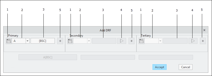
Add DRF (ASME)
1. Display Datum from Targets Properties — For a
datum from
targets, this button launches a window that shows the values for the locating basic dimensions for the targets. This button is only enabled for datums from targets that are referenced in a fully constrained
DRF.
2. Datum Feature Selector — Contains a filtered list of all applicable
datum features and datum from targets.
3. Datum Feature Material Boundary Modifier — Allows you to specify a
material boundary modifier for the datum feature. This control is disabled when it is not applicable.
5. Add a Datum Feature — When defining a datum from multiple datum features (e.g., coaxial datum features A-B), click this button to access the controls to specify an additional datum feature.
When specifying the datum features for a DRF, the Datum Feature Selector contains a filtered list of the applicable datum features so that only valid combinations of datum features are allowed. Keep in mind that not all datum features may be referenced as the primary datum in a DRF (see the notations in the 'Datum Feature?' column in
Feature Descriptions).
Why does this dialog window sometimes appear automatically?
GD&T Advisor automatically adds a DRF to the model whenever you add a datum feature to the model that is capable of more fully constraining the part than any of the existing DRFs. If the added datum feature is a feature of size, a material condition modifier (<RFS>, Ⓜ, or Ⓛ) for that datum feature is required to fully define the DRF. By default, the datum feature material condition is made equal to the tolerance zone material condition modifier specified (if applicable) for the geometric tolerance applied to the feature. If the no geometric tolerance that requires a material condition modifier is applied to the feature (e.g., the first feature in the model) then this dialog window pops up automatically so you can specify the desired material condition modifier for the datum feature.

