About Routing Cables
Use the Route Cables dialog box to build a set of one or more cables to route. You can choose from the following items:
• 
,

,

—Create new wires and cables
• 
—Search for cables in the design that needs to be routed.
• Select partially routed cable features.
Defining Cable Connections
When utilizing logical data, the From and To boxes are automatically populated. However, you must set the start (From) and end (To) entry ports for the wires, cables and (optionally) conductors while defining the cable design manually. Once valid start and end locations are defined the system can route the wires, cables, and conductors.
Routing Options
Use one of the following options to determine how you want to route the selected items between the start and end locations.
• Simple Route—Routes a single segment for each wire or cable between the defined start and end locations. You insert intermediate locations later and use the Reroute tab to define the trajectory of the route.
• Via Network—Autoroutes the cables through the network. The wires automatically follow the shortest path through the network.
|  You can pause routing and use the Route Network tab to create or change a network. |
• Follow Cable—Routes the selected cables and conductors along the path of a previously routed cable. Select the
Cable to Follow from the graphics window or Model Tree, or use the
Search Tool dialog box (
Tools >
Find). Select the
From and
To locations on the cable.
• Follow Pipeline—Routes the selected cables and conductors through a pipe centerline. Select the Pipe to Follow from the graphics window or Model Tree. Select a pipe end or a free fitting port as the From and To locations.
| You must select the pipeline before selecting the From and To locations. |
When you use a simple path you define the entry port ends of the conductors and specify the locations of the cable jacket. You cannot route a cable jacket to entry ports. Locations for the cable jacket can be on the network, existing locations in the cabling assembly, or defined on the fly while routing.
To Route Cables
1. Click

. The
Route Cables dialog box opens.
| If you use logical data and have undesignated components in the assembly, you are prompted to designate them before the dialog box opens. Click No to leave them undesignated, or click Yes to open the Auto Designator dialog box. |
2. Do one of the following:
◦ Click
to route a new cable,
to create a new wire, or
to create a new ribbon cable.
◦ Click

to retrieve cables from the assembly or from a logical reference. The
Find Cables dialog box opens. Select the cables and click
OK.
| • To route a wire or cable, you must create a corresponding spool. • When a selected cable contains multiple segments, you are prompted to join them before the cable is added to the list. |
3. Select a
Route Type from the
list.
4. When the cable and conductors do not have a logical reference, click the collector or use the right-click shortcut menu in the graphics window and select From or To. You can select an entry port, coordinate system, or a connector.
| To route a wire to a connector, the connector must be designated. |
5. Click Apply to route the cable or conductor. The routed cable is removed from the cable list.
6. After you finish routing wires and cables, click OK.
Tips for Routing Cables
• To select an undesignated coordinate system, right-click in the graphics window or click the arrow next to the box and select Allow undesignated CSYS. Click OK to designate the entry port and middle click to use the default parameters.
• While using logical data, open the Route Cables dialog box and select a designated connector to view the list of cables and wires that are connected to the selected connector.
• To control the start and end locations of a cable jacket, place your cursor over the From box, right-click and choose Add location. Select a location in the model and repeat the process to set the To location.
• To edit an existing cable, select a cable in the Model Tree or graphics window, right-click, and click
. The
Route Cables dialog box opens.
• To leave a wire unterminated, right-click in the graphics window or click the arrow next to the To box and select Add Location to add a new location, or Allow Location to select an existing location.
• To remove a cable from the list, right-click and choose Remove from the shortcut menu.
• When the cable and conductors do not have a logical reference, you can route a conductor as a shield. Right-click a conductor and choose Route as Shield from the shortcut menu.
Routing a Cable to Follow a Conduit
When you route a cable by following a pipeline, the cables and wires follow the entire pipeline and can only enter and exit at pipeline ends. The choice of To locations is restricted to those that can be routed to by following the pipeline centerlines. The cable can change direction at elbows, tees, and crosses. The length of the cable following a pipe centerline is calculated to be equal to the length of the centerline. Cable portions cannot be drawn inside the pipe.
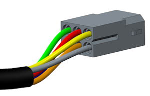
Routing Individual Cable Conductors
You can route each conductor of the cable separately to connect it to a port on a connector, as shown in the illustration below. You must have a coordinate system at the location of every port.
For manually created cables, terminate individual conductors at the required coordinate system.
For cables created using logical data, the connectivity is automatic. Ensure that every pin in the schematic connector contains unique coordinate system reference.
Tips
• To route individual conductors, you must set the NUM_CONDUCTORS parameter with an appropriate value for the respective cable spool.
• In order for cable to fan out from the cable jacket, it must start and end at locations that are not entry ports. This can be accomplished by routing via a network or adding locations when routing the cable.
• When autorouting cables, set the configuration option cable_jacket_termination to Network ends*.
To Find Cables
1. In the
Route Cables dialog box, click
. The
Find Cables dialog box opens.
2. Expand Options to display the search options.
3. Click the appropriate check boxes. The items that are found are listed in the items found section of the Find Cables dialog box.
4. Select a Cable type:
◦ Whole Cables—Displays cables and wires in a list without listing individual conductors.
◦ Conductors—Displays individual cable conductors in the list, the wires in the cable.
| Click either the Include cables or Include ribbon cables check box for the cable types to be available. |
5. Select the items to add to the cables in the
Route Cables dialog box from the
items found section and click

.
6. To remove an item from the
items selected section click

.
7. Click OK.