To Create a Tree Definition Structure
This procedure walks you through creating a generic symbol with a multi level structure.
1. On the
Annotate tab, click the arrow next to
 Symbol
, and click
 Symbol Gallery
. The
SYM GALLERY menu appears on the Menu Manager.
2. Click Define.
3. Type the symbol name, [FILLET]. A second window opens with the Menu Manager open to the SYMBOL EDIT menu. Use this window to create the symbol.
4. Use the drafting tools to create new geometry.
5. Click SYMBOL EDIT > Groups > Create.
6. Type the group name as ARROW_SIDE. Select all of the entities that belong to the arrow side except the reference line. The system does not include the reference line in any group because it must appear in all symbol instances. After you select all entities, click OK.
7. To create another top-level group, choose SYM GROUPS > Create, type the name of the group [OTHER_SIDE], and select entities located on the other side of the reference line. After you select all entities, click OK.
8. For this example, top-level groups are exclusive. Click SYM GROUPS > Group Attr Exclusive.
9. To create subgroups of the top-level groups, choose SYM GROUPS > Change Level.
10. The TOP LEVEL menu displays the list of groups at the current level and the This Level command. Click ARROW_SIDE; all entities pertaining to this group appear in the symbol edit window.
11. Click ARROW_SIDE and click This Level.
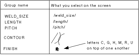
12. To specify subgroups at the current level, choose Create, type the group name, and select the corresponding geometry or text line. When creating subgroups, use the following table:
|  The system does not include the fillet in any subgroups because it must always be in any arrow-side instance. |
By default, the system sets the group attribute to Independent; therefore, you do not have to use the GROUP ATTR menu. Groups are independent because you can include all groups in a single instance.
1. To specify the subgroups of the group CONTOUR, choose Change > Level > CONTOUR. The symbol edit window displays entities from the current group.
2. Click SYM GROUPS > Create. Create these three groups:
3. Click SYM GROUPS > Group Attr > Exclusive (you can choose only one of the preceding subgroups under the group CONTOUR at one time).
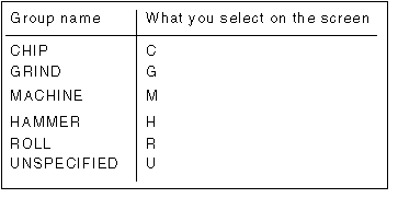
4. Click Change Level > UP > FINISH. To select the proper character on the screen, use Query Sel. Create groups as follows:
5. Click SYM GROUPS > Group Attr > Exclusive. You have completely described the symbol along the arrow-side branch.
6. To specify subgroups along the other-side branch, chooseChange Level > UP to return to the TOP LEVEL menu.
7. Click OTHER_SIDE and proceed to create groups, following a procedure similar to the one described in Steps 8 through 19.
8. When you finish the symbol definition, choose SYM GROUPS > Done.
9. Click SYMBOL EDIT > Attributes.
10. From the Symbol Definition Attributes dialog box, select items characterizing the attachment point, leader type, and symbol size. For this example, click Left Leader and Variable.
11. Select the leader origin on the left side of the symbol; then click OK.
12. Click the Variable Text tab to type values for notes created between slashes as variable text entries.
13. The system informs you that it has defined the symbol. To save the generic symbol on a disk, choose SYMBOL EDIT > Write. Type the directory path or accept the default.
 Symbol, and click
  Symbol Gallery. The SYM GALLERY menu appears on the Menu Manager.
 Symbol, and click
  Symbol Gallery. The SYM GALLERY menu appears on the Menu Manager.
 Symbol, and click
  Symbol Gallery. The SYM GALLERY menu appears on the Menu Manager.

