|
On Entity
|
Creates a leader that is attached to a model edge or draft geometry. Selecting the entity near its vertex locates the leader at the vertex.
|
|
|
On Surface
|
Locates the leader on model geometry or surfaces. You can select model geometry, threads, and datum surfaces. Once you make an attachment on a surface, if you reorient the view, the attachment remains. If the size of the surface changes, the system updates the leader point accordingly.
|
|
|
Free Point
|
Locates the leader anywhere in the drawing. You can create a note using this command only in Detailed Drawings.
|
|
|
Midpoint
|
Locates the leader at the midpoint of a model edge or draft geometry.
|
|
|
Intersect
|
Locates the leader at the intersection of two model edges or two draft entities.
|
|
 Automatic Automatic |
Sets the default arrow style for new leaders.
|
|
 None None |
Creates a leader with no arrow.
|
 |
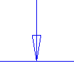
 Single Arrow Single Arrow |
Creates a leader with an arrow head.
|
 |
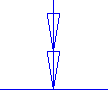
 Double Arrow Double Arrow |
Creates a leader with a double arrow head.
|
 |
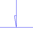
 Half Arrow Half Arrow |
Creates a leader with a half arrow head. To flip the half arrow to the opposite side of the leader attachment point, select the half arrow, right-click, and click Flip Half Arrow on the shortcut menu.
|
 |
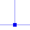
 Filled Box Filled Box |
Creates a leader with a filled box.
|
 |
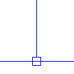
 Open Box Open Box |
Creates a leader with a box.
|
 |
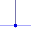
 Filled Dot Filled Dot |
Creates a leader with a filled dot.
|
 |
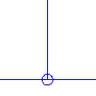
 Dot Dot |
Creates a leader with a dot.
|
 |
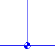
 Target Target |
Creates a leader with a target.
|
 |
 Triangle Triangle |
Creates a leader with a triangle. You can control the display of the Triangle arrow head as filled or open by using the set_datum_triangle_display detail option.
|
 |
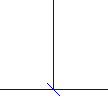
 Slash Slash |
Creates a leader with a slash.
|
 |
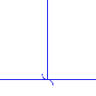
 Integral Integral |
Creates a leader with an integral.
|
 |
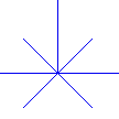
 Cross Cross |
Creates a leader with a cross.
|
 |
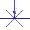
 Cross and Arrow Cross and Arrow |
Creates a leader with a cross and an arrow.
|
 |