Tutorial 4: Creating a Multimaterial Molded Housing of an Electronic Device
In this tutorial you assign different materials to different bodies in a part. You then set different cross-section hatching patterns for each material to appear in a cross section. In this tutorial you place a user-defined feature and assign it to a body in the part.
• It is recommended that you work through the exercises sequentially during one Creo Parametric session. • In the exercises that follow you are instructed to use commands from the ribbon. After selecting items, you can also access these commands from the mini toolbar or by right-clicking. • In the videos of the exercises, to exit a tool a middle-click was used instead of  in many instances. in many instances. |
This tutorial is divided into 4 exercises to make it easier to follow:
• Exercise 1: Set a Different Material—Different bodies are assigned different materials.
• Exercise 2: Place a User-Defined Feature (UDF)—Place a UDF in the part and add it to a body.
• Exercise 3: View the Cross-Section Hatching Pattern from the Library in a Material Definition—Use a cross-section hatching pattern from the library.
• Exercise 4: Create Different Cross-Section Hatching Patterns—Create cross-section hatching patterns specific to a body.
Exercise 1: Set a Different Material
Watch a video that demonstrates the steps in this exercise:
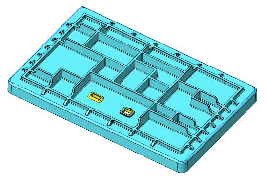
1. Set the working directory to tutorial4. and open mb_multimat_inj_molded_demo.prt.
2. Click  and clear the (Select All) check box to turn off datum display in the graphics window.
and clear the (Select All) check box to turn off datum display in the graphics window.3. In the Model Tree, expand the  Materials node. The materials assigned to the part appear.
Materials node. The materials assigned to the part appear.4. Right-click PA66-GF, and select Set as Master. A blue arrow ( ) appears next to PA66-GF setting it as the master material.
) appears next to PA66-GF setting it as the master material.5. Click OK when prompted.
6. Expand the body nodes. Both bodies are assigned the same material.
By default, a body is assigned the master material of the part. You can explicitly assign a different material to a body. |
7. Select body OVERMOLD, right-click, select Assign Material, and click SILICON_RUBBER. The material assigned to the body is now SILICON_RUBBER.
Assign Material, and click SILICON_RUBBER. The material assigned to the body is now SILICON_RUBBER.This concludes the first of 4 exercises.
Exercise 2: Place a User-Defined Feature (UDF)
Watch a video that demonstrates the steps in this exercise:
1. Click and select the  Csys Display check box. Coordinate systems display.
and select the Csys Display check box. Coordinate systems display.2. In the Model Tree, expand  Group HOUSING_BASE.
Group HOUSING_BASE.3. Click User-Defined Feature. The Open dialog box opens.
User-Defined Feature. The Open dialog box opens.4. Select cutout_port_w_overm_type_a.gph and click Open. The Insert User-Defined Feature dialog box opens.
5. Make sure Advanced reference configuration is selected and click OK. The User Defined Feature Placement dialog box opens.
6. For the Coordinate System reference, select the CSO coordinate system in the graphics window.
7. For the first surface, select the top surface of the Housing body.
8. For the second surface, select the bottom surface of the Housing body.
9. For the first body, select Housing
10. For the second body, select Overmold1.
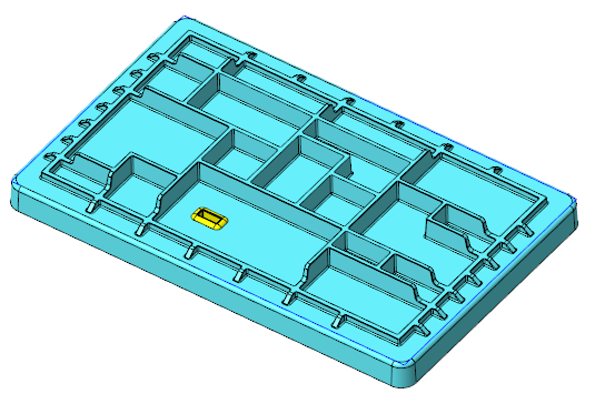
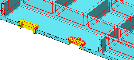
11. Click . The UDF is placed in the part. Placement of the UDF contributes to changes in geometry in both bodies.
. The UDF is placed in the part. Placement of the UDF contributes to changes in geometry in both bodies.This concludes the second of 4 exercises.
Exercise 3: View the Cross-Section Hatching Pattern from the Library in a Material Definition
Watch a video that demonstrates the steps in this exercise:
1. Expand the HOUSING body, right-click PA66-GF, and select  Edit Definition. The Material Definition dialog box opens after you click OK in the message.
Edit Definition. The Material Definition dialog box opens after you click OK in the message.2. Click Miscellaneous to display properties of the material.
3. In the Detailing section, note that the Cross Hatching is ISO plastic (DIN ISO 128-50 SP).
4. Click OK.
This concludes the third of 4 exercises.
Exercise 4: Create Different Cross-Section Hatchings
Watch a video that demonstrates the steps in this exercise:
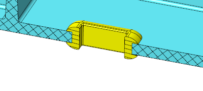
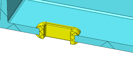
1. Zoom in to the area of body Overmold1.
2. In the Model Tree, select XSEC001, right-click, and select  . The cross section shows in the graphics window.
. The cross section shows in the graphics window.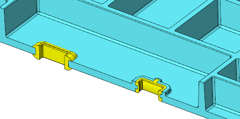
Click  to deactivate the cross section. to deactivate the cross section. |
3. In the Model Tree, select XSEC001, right-click, and select  . The default cross-section hatching shows on the model.
. The default cross-section hatching shows on the model.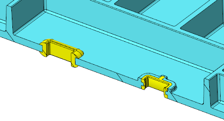
4. Right-click again, and select  . The Edit Hatching dialog box opens.
. The Edit Hatching dialog box opens.5. Select body HOUSING. The options in the Edit Hatching dialog box become available.
6. From the Hatch Patterns list in the box, select ISO thermoset plastic (DIN ISO 128-50 SP2).
7. Click Apply. The cross-section hatching shows on the body.
8. Click  until you see in the pattern in the following picture.
until you see in the pattern in the following picture.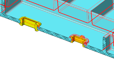
When you click . the space between the lines of hatching decreases with each click. When you click  the space between the lines of hatching increases with each click. the space between the lines of hatching increases with each click. |
9. In the Apply settings for list, select  Part.
Part.
Part.10. Select Use material hatch from the Hatching Options list. The cross-section hatching pattern assigned to the body’s material shows (ISO plastic (DIN ISO 128-50 SP)).
11. In the Apply settings for list, select  Body.
Body.
Body.12. Click body Overmold1.
13. From the Hatching Options list, select Copy hatch pattern.
14. Select body HOUSING. Note that the cross-section hatching pattern continues from the HOUSING body.
15. In the Apply settings for list, select Part.
Part.16. Select Use material hatch from the Hatching Options list. The cross-section hatching pattern assigned to the body’s material shows.
17. Click until you see in the pattern in the following picture.
until you see in the pattern in the following picture.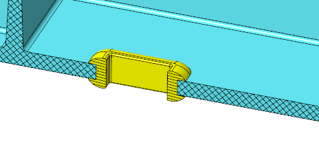
This concludes tutorial 4.