About Diagram
Diagram captures logical connection information and represents it graphically as wires, cables, components and pins. You can use Diagram to output component lists and wire lists, either as schematic reports or as formatted ASCII text files.
Diagram-specific tools allow you to:
• Use symbol libraries of electrical and mechanical components.
• Perform quick and easy routing of connections between components with automatic generation of wire lists.
• Compare the diagram to its corresponding cabling assembly or wirelist information from an ASCII file.
• Organize the diagram by layers. You can place wires, connectors, and cables on a layer, even if they are on different sheets.
• Produce BOMs and wire and connection lists that you can pass to Cabling.
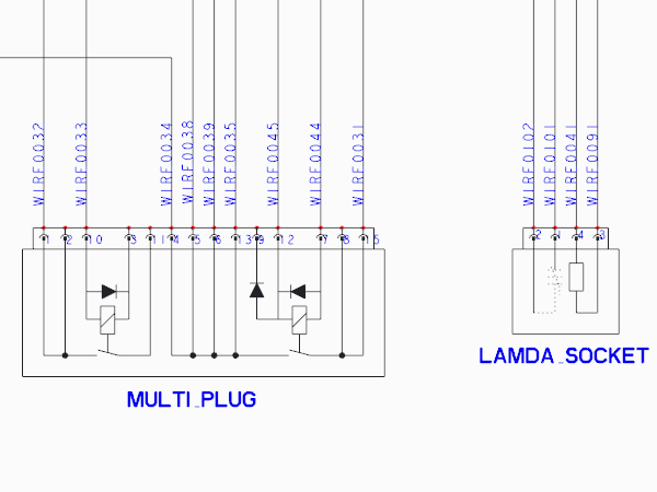
A basic wiring diagram showing connectors, nodes, wires wire labels and wire breaks.
Additional standard tools in Diagram include the ability to add formats, draft geometry, and notes. Also, all standard Creo Parametric import and export functions, such as IGES and DXF, and all standard plotting options are available within the Diagram environment.

