Example: Silhouette edges of faces
In the Sketch mode, when the Project tool is activated, the model geometry available for projection is highlighted when the mouse cursor hovers over it. The highlighted geometry could be selected by the left mouse button in order to be projected onto the current sketch.
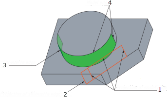
When a face is highlighted and selected to be projected onto the current sketch plane, all the edges of the selected surface as well as silhouette edges available for the selected surface are automatically detected and projected.
After projection, a number of sketch entities are generated on the sketch plane. Every projected sketch entity is obtained by the projection of corresponding model edge or silhouette edge.
1. Projection of model edge
2. Projection of silhouette edge
3. Silhouette edge
4. Model edge